Rain sensor

a sensor and rain drop technology, applied in the field of rain sensors, can solve the problems of difficult for the controller b>140/b> to extract the edges of rain drops, and the difficulty of the controller b>140/b> to extract the edges of mud, and achieve the effect of higher accuracy

Active Publication Date: 2010-01-12
DENSO CORP
View PDF17 Cites 58 Cited by
  • Summary
  • Abstract
  • Description
  • Claims
  • Application Information

AI Technical Summary

Problems solved by technology

In this case, it is difficult for the controller 140 to extract edges of the rain drops.
In another case that a mud splash causes a large amount of mud to be attached to the windshield 10, it is also difficult for the controller 140 to extract edges of the mud.

Method used


Image

  • Rain sensor
  • Rain sensor
  • Rain sensor

Examples


Embodiment Construction

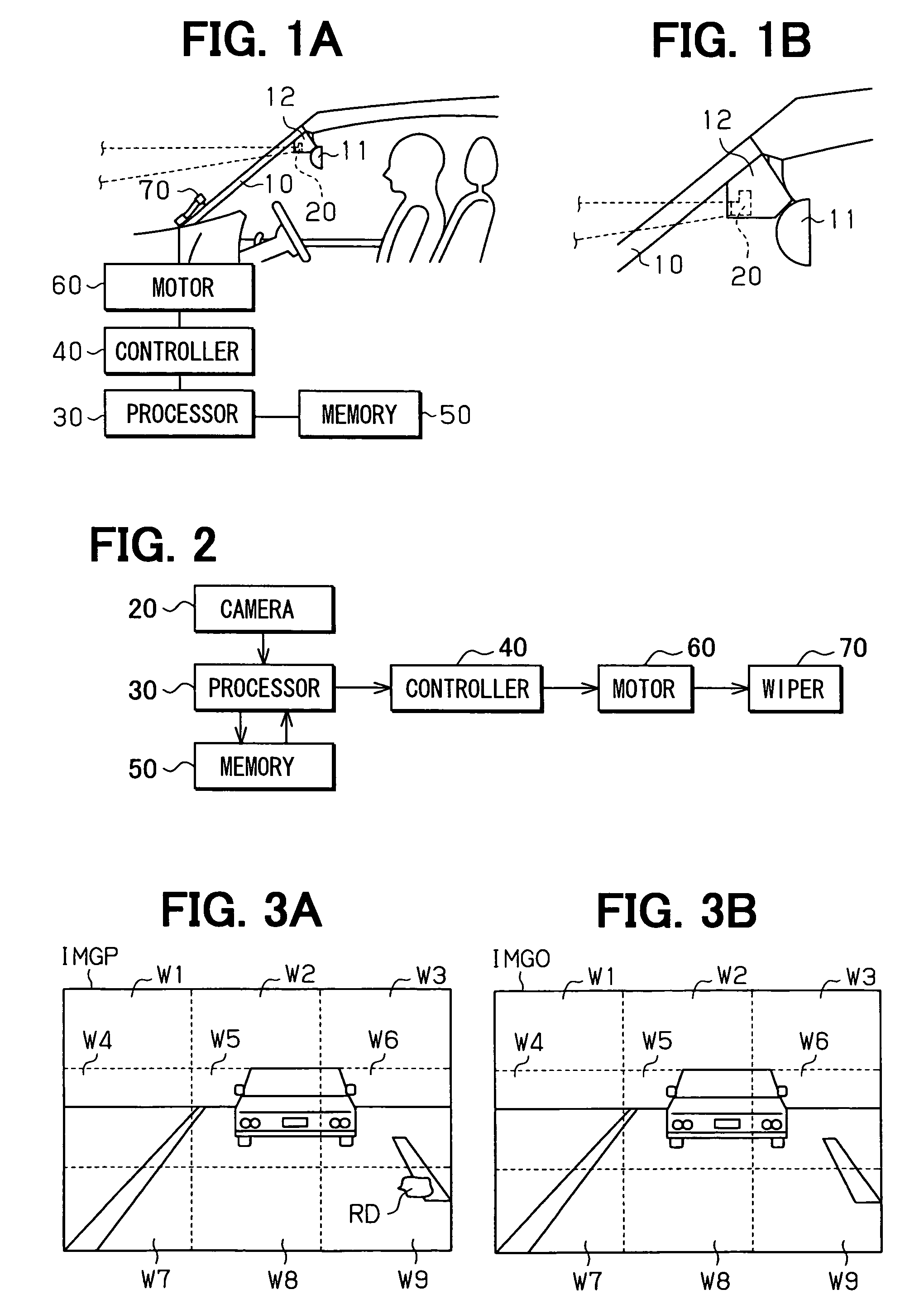
[0026]Hereinafter, a rain sensor according to an embodiment of the present invention will be described with reference to FIGS. 1A to 4. The rain sensor has a structure similar to the conventional rain sensor of prior art shown in FIG. 9. However, there are differences between the rain sensor of the present invention and that of prior art in several aspects such as a camera having an infinite focal length that will be explained below.

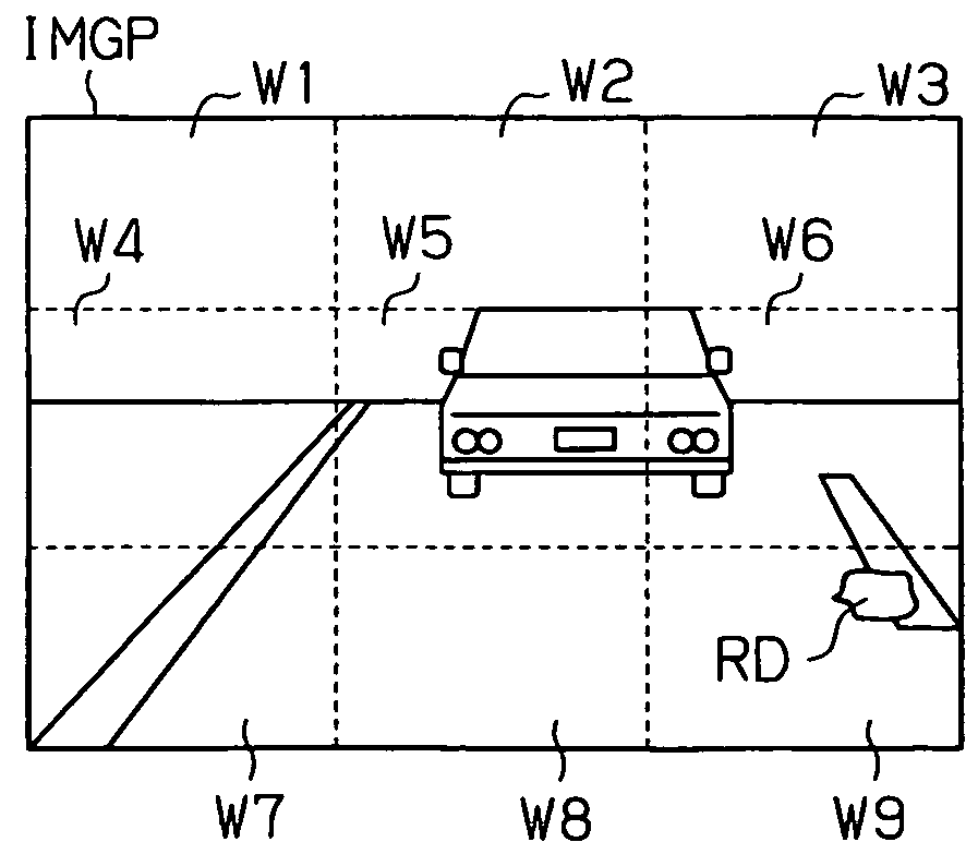
[0027]As shown in FIGS. 1A, 1B, and 2, a rain sensor of this embodiment used for a vehicle includes a casing 12, a camera 20, an image processor 30 as a processor unit, a controller 40, and a memory 50. The casing 12 is placed between a windshield 10 and a rearview mirror 11, and attached to a surface of the windshield 10 facing a passenger's compartment. The camera 20 is installed in the casing 12 and takes an image of an exterior of the vehicle (or a scene outside of the vehicle) with an infinite focal length through the windshield 10.

[0028]The image p...


PUM


Abstract

A rain sensor provided in a vehicle includes a camera and a processor. The camera takes an image of a scene outside of the vehicle through a windshield of the vehicle with an infinite focal length. The processor detects rain based on a variation degree of intensities of pixels in the image from an average intensity of the pixels.

Description

CROSS REFERENCE TO RELATED APPLICATION[0001]This application is based on and incorporates herein by reference Japanese patent application No. 2005-113497 filed on Apr. 11, 2005.FIELD OF THE INVENTION[0002]The present invention relates to a rain sensor for detecting rain.BACKGROUND OF THE INVENTION[0003]In JP 2001-147278A, a rain sensor provided in a vehicle is disclosed which detects rain drops by including a camera 20, an image processor 130, a controller 140, and a memory 150 (shown in FIG. 9).[0004]The camera 20 takes an image of a predetermined area in a windshield 10 of the vehicle. The image processor 130 obtains a binarized image by processing the image taken by the camera 20. The controller 140 stores the binarized image into the memory 150. Every time the image processor 130 obtains a binarized image of the predetermined area, the controller 140 determines an amount of rain W on the windshield 10 based on the currently binarized image and a previously binarized image stored...

Claims


Application Information

Patent Timeline
Patent Type & Authority Patents(United States)
IPC IPC(8): G06K9/00
CPCB60S1/0822B60S1/0844G06V20/56B60S1/08B60S1/02
Inventor TSUKAMOTO, TAKESHI
Owner DENSO CORP
Why Eureka
Try Eureka