
Rain sensor

Inactive Publication Date: 2011-08-25
NILES PARTS CO LTD
View PDF5 Cites 27 Cited by
  • Summary
  • Abstract
  • Description
  • Claims
  • Application Information

AI Technical Summary

Benefits of technology

[0009]According to the present invention, the captured image in the detection region to which light is emitted from the light emission unit is totally bright and the captured image in the detection region to which light is not emitted is totally dark. If raindrops adhere to the detection region, only the portion has a brightness which reflects the landscape around the vehicle reflected in the raindrops. Thereby, the portion of the raindrops adhering to the detection region can be discriminated from other portions excluding raindrops based on the contrast therebetween, enabling adequate detection of only raindrops without being affected by the peripheral landscape reflected in the raindrop in detecting raindrops.

Problems solved by technology

In such a case, the device disclosed in said Japanese Patent Application may not detect the part of the raindrop reflecting the landscape around the vehicle as the raindrop because the part thereof is not different from the white portion in processing the image.

Method used


Image

  • Rain sensor
  • Rain sensor
  • Rain sensor

Examples


Embodiment Construction

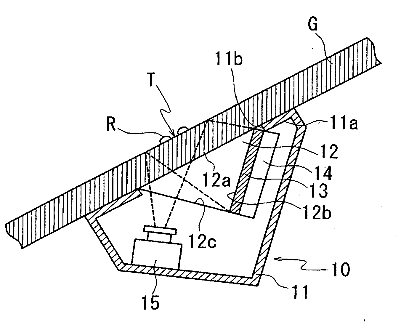
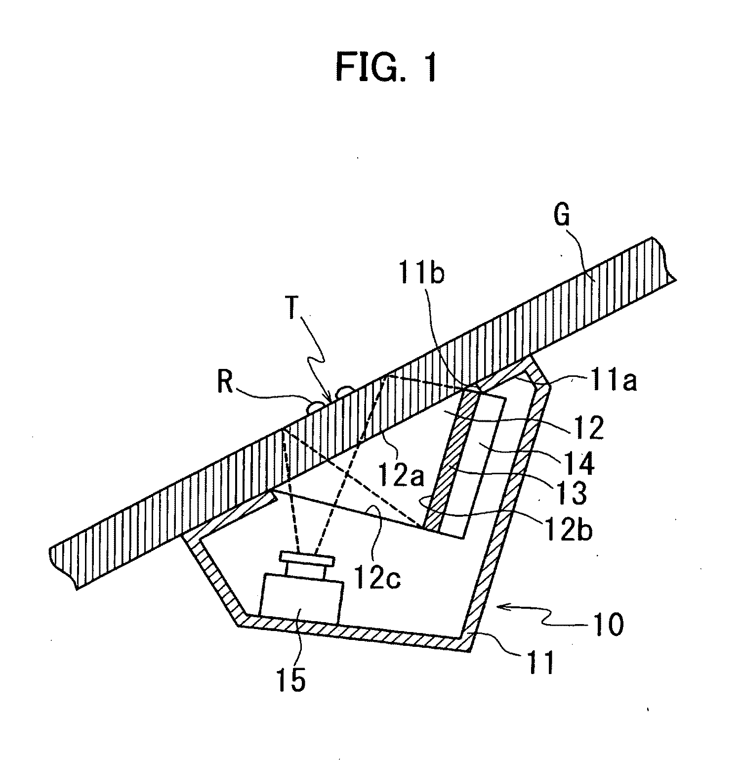
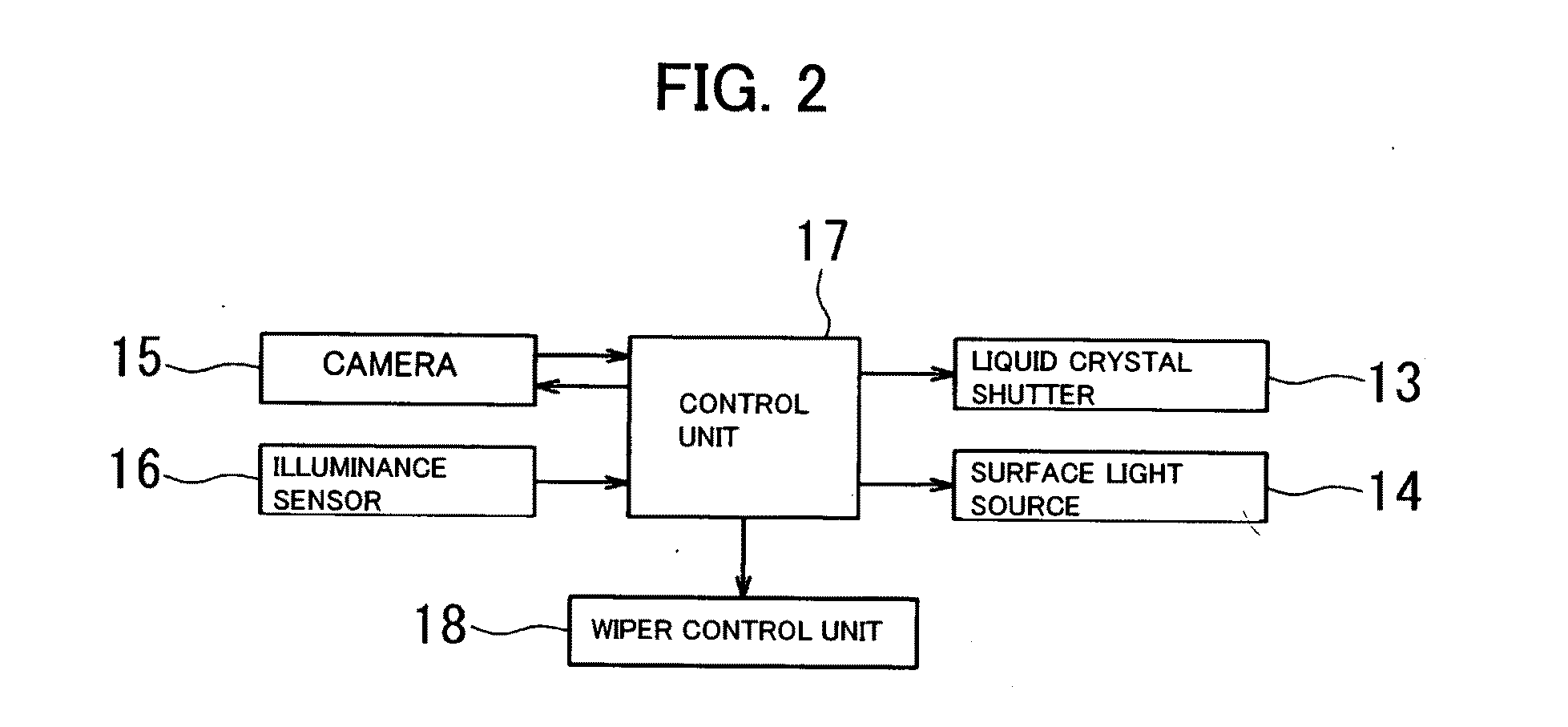
[0022]The embodiment of the present invention is described below. FIG. 1 is a schematic diagram showing a configuration of the rain sensor according to the embodiment and viewed from the cross sectional direction of a windshield to which the rain sensor is attached. FIG. 2 is a circuit block diagram of the rain sensor.

[0023]A rain sensor 10 is fixed to the surface of a windshield G on the side of a vehicle compartment with an adhesive (not shown) or an adhesive sheet. A main body case 11 for the rain sensor 10 is formed of a resin material which does not transmit light. The main body case 11 incorporates a rectangular prism 12, a liquid crystal shutter 13, a surface light source 14, and a camera (CCD camera) 15.

[0024]The rectangular prism 12 forms an isosceles right triangle, when viewed from the cross section thereof. An opening 11b for exposing the hypotenuse face 12a of the rectangular prism 12 is provided in the front wall 11a of the main body case 11. The hypotenuse face 12a of...


PUM


Abstract

There is provided a rain sensor capable of adequately detecting raindrops in a captured image. The rain sensor includes: a surface light source 14 which emits light to a windshield G to cause light to be incident on a raindrop detection region T set on the windshield G at a critical angle or more; a camera 15 which is arranged on the optical path of light totally reflected by the detection region T and captures the detection region T; and a detection unit which detects raindrops adhering to the detection region T from contrast in the image captured by the camera 15; the detection unit detects the raindrops adhering to the detection region T based on at least one of the captured image in the detection region T to which light is emitted from the surface light source 14 and the captured image in the detection region T to which light is not emitted from the surface light source 14.

Description

BACKGROUND OF THE INVENTION[0001]1. Field of the Invention[0002]The present invention relates to a rain sensor.[0003]2. Description of the Related Art[0004]Various rain sensors have been proposed which detect a rainfall based on raindrops adhering to the windshield of a vehicle. A device disclosed in Japanese Patent Application Laid-Open No. 2007-0127595 is employed in the rain sensor to be used as an device for detecting raindrops adhering to a windshield.[0005]The device disclosed in Japanese Patent Application Laid-Open No. 2007-0127595 is configured such that a white member is provided on the surface of a windshield inside a vehicle compartment, the area of the windshield where the white member is provided is picked up by a camera outside the vehicle compartment and the picked up image is processed to detect the raindrops adhering to the windshield from the difference between a white portion and a peripheral landscape reflected by the adhering raindrops.[0006]However, a raindrop...

Claims


Application Information

Patent Timeline
IPC IPC(8): G01W1/00H01L31/12H01L27/146
CPCH01L27/14678B60S1/0844G06V20/56
Inventor TAOKA, TETSUO
Owner NILES PARTS CO LTD
Learn More