

Image formation apparatus
a technology of image formation apparatus and auxiliary components, which is applied in the direction of electrographic process apparatus, instruments, optics, etc., can solve the problem of not being able to detect the used condition of the image formation apparatus including the condition of consumable components other than toner
- Summary
- Abstract
- Description
- Claims
- Application Information
AI Technical Summary
Benefits of technology
Problems solved by technology
Method used
Image

Examples
first embodiment
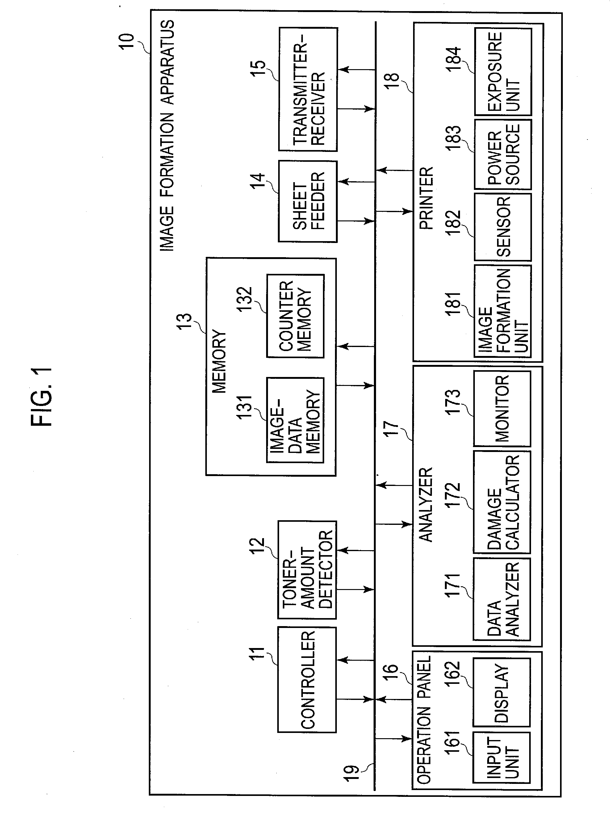
[0032]FIG. 1 is a block diagram schematically illustrating the configuration of image formation apparatus 10 according to a first embodiment. Image formation apparatus 10 includes controller 11, toner-amount detector 12, memory 13, sheet feeder 14, transmitter-receiver 15, operation panel 16, analyzer 17, printer 18, and bus 19 that connects the above-mentioned members to one another.
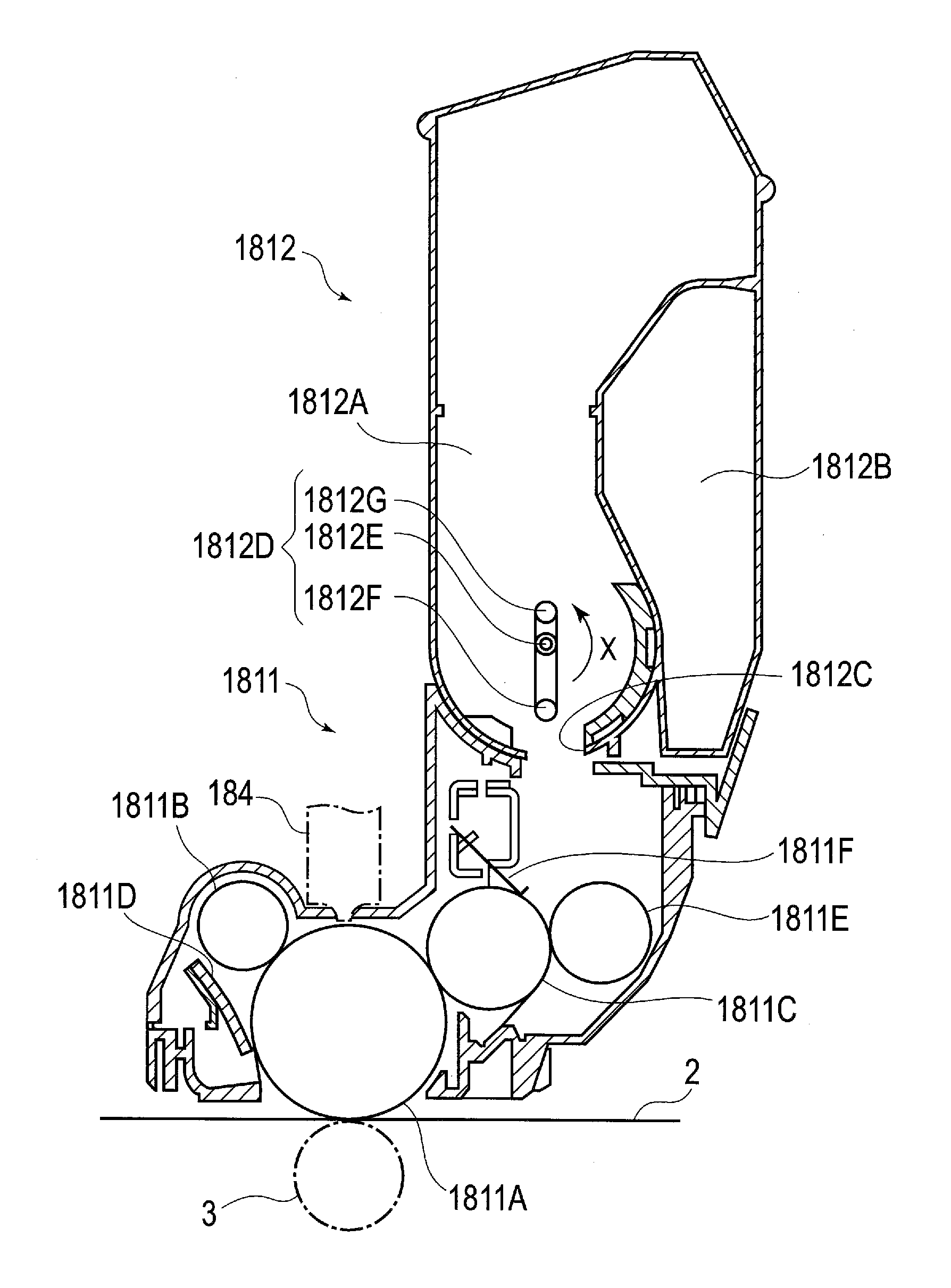
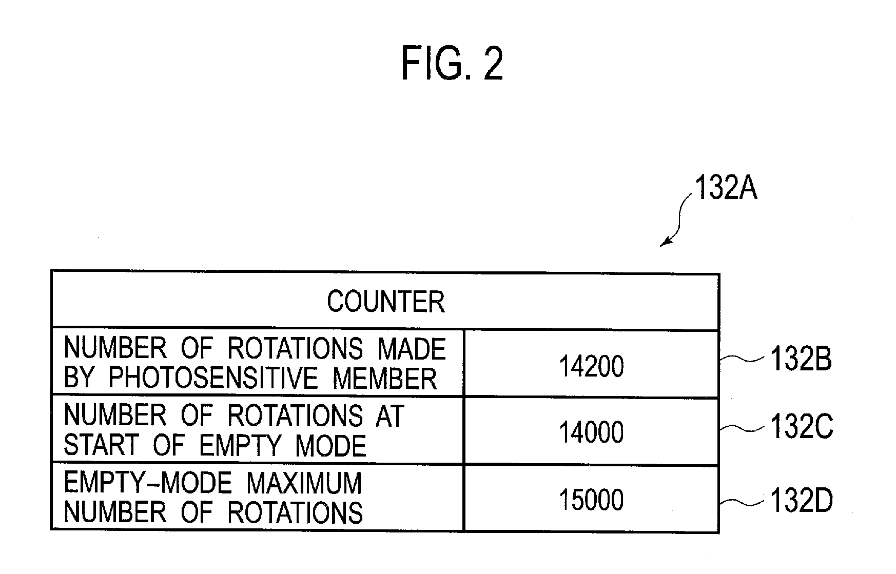
[0033]Controller 11 performs an overall control of the operations of the other components of image formation apparatus 10. In addition, controller 11 counts the number of rotations made by photosensitive member 1811A (see FIG. 3) included in printer 18, and then updates the number of rotations made by photosensitive member 1811A stored in counter memory 232. On the basis of the detection result obtained by sensor 182 included in printer 18, toner-amount detector 12 detects the amount of toner (remaining toner) that remains in toner cartridge 1812 (see FIG. 3). Memory 13 stores information that is necess...
second embodiment
[0066]FIG. 11 is block diagram schematically illustrating the overall configuration of image formation apparatus 20 according to a second embodiment. As shown in FIG. 11, image formation apparatus 20 includes controller 21, toner-amount detector 12, memory 23, sheet feeder 14, transmitter-receiver 15, operation panel 16, analyzer 27, printer 18, and bus 19 that connects these components to one another. Image formation apparatus 20 according to the second embodiment differs from image formation apparatus 10 according to the first embodiment in that image formation apparatus 20 includes controller 21, memory 23, and analyzer 27. In image formation apparatus 20 according to the second embodiment, damage calculator 272 calculates the damage-progress rate of image drum unit 1811 by adding predetermined values corresponding to the dot-count numbers involved in the print jobs and thus the accuracy of the calculation of the damage-progress rate of image drum unit 1811 is improved. To put it...
third embodiment
[0087]FIG. 15 is a block diagram schematically illustrating the configuration of image formation apparatus 30 according to the third embodiment. As shown in FIG. 15, image formation apparatus 30 includes controller 11, toner-amount detector 12, memory 33, sheet feeder 14, transmitter-receiver 15, operation panel 16, analyzer 37, printer 18, and bus 19 that connects these components to one another. Image formation apparatus 30 according to the third embodiment differs from image formation apparatus 10 according to the first embodiment in that image formation apparatus 30 includes memory 33 and in analyzer 37. In image formation apparatus 30 according to the third embodiment, display unit 162 displays a screen containing information on the consumption rate of an image drum unit when toner-amount detector 12 detects the fact that only a small amount of toner is left in a toner cartridge.
[0088]Memory 33 according to the third embodiment includes image-data memory 131 and counter memory ...
PUM
 Abstract
Description
Claims
Application Information