Engine misfire detection apparatus for internal combustion engine and engine misfire detection method

a technology for internal combustion engines and misfire detection equipment, which is applied in the direction of electrical control, ignition automatic control, instruments, etc., can solve the problems of inadequate or inaccurate detection of misfires of internal combustion engines, failure to detect misfires, etc., and achieve adequate and accurate detection

Active Publication Date: 2009-03-17
TOYOTA JIDOSHA KK
View PDF21 Cites 15 Cited by
  • Summary
  • Abstract
  • Description
  • Claims
  • Application Information

AI Technical Summary

Benefits of technology

[0007]The engine misfire detection apparatus of the invention sequentially calculates the rotational fluctuations at the crank angles corresponding to the respective ignition timings of the plural cylinders in the internal combustion engine, based on the rotational positions of the crankshaft of the internal combustion engine. The engine misfire detection apparatus then computes the first rotational fluctuation difference and the second rotational fluctuation difference. The first rotational fluctuation difference represents the difference between each of the rotational fluctuations sequentially calculated at the corresponding crank angles and a rotational fluctuation calculated at a crank angle prior to each of the corresponding crank angles by a preset first angle. The second rotational fluctuation difference represents the difference between each of the rotational fluctuations sequentially calculated at the corresponding crank angles and a rotational fluctuation calculated at a crank angle prior to each of the corresponding crank angles by a preset second angle that is different from the preset first angle. The engine misfire detection apparatus detects a misfire of the internal combustion engine based on the computed first rotational fluctuation difference and the computed second rotational fluctuation difference, during the time period from the start of the internal combustion engine to satisfaction of the predetermined condition. Namely the engine misfire detection apparatus takes advantage of the rotational fluctuation differences from the rotational fluctuations at different prior crank angles. This arrangement ensures adequate detection of the misfire of the internal combustion engine during the time period from the start of the internal combustion engine to satisfaction of the predetermined condition. The ‘predetermined condition’ may be completion of warm-up of a catalyst included in an exhaust emission control unit of the internal combustion engine. This arrangement ensures adequate and accurate detection of the misfire of the internal combustion engine even during operation of the internal combustion engine to warm up the catalyst included in the exhaust emission control unit. The ‘internal combustion engine’ may be driven at a start with a delayed ignition timing for warming up the catalyst included in the exhaust emission control unit of the internal combustion engine. This arrangement ensures adequate and accurate detection of the misfire of the internal combustion engine even during operation of the internal combustion engine with the delayed ignition timing for warm-up of the catalyst included in the exhaust emission control unit.
[0009]In the engine misfire detection apparatus of the invention which detects the misfire of the internal combustion engine when the first rotational fluctuation difference is not less than a preset first value and when the second rotational fluctuation difference is not less than a preset second value, the engine misfire detection module may detect the misfire of the internal combustion engine, when a proportion of a first object rotational fluctuation difference, which is selected as one first rotational fluctuation difference of not less than the preset first value, to another first rotational fluctuation difference other than the first object rotational fluctuation difference is in a predetermined first misfire identification proportion range and when a proportion of a second object rotational fluctuation difference, which is selected as one second rotational fluctuation difference of not less than the preset second value, to another second rotational fluctuation difference other than the second object rotational fluctuation difference is in a predetermined second misfire identification proportion range that is different from the predetermined first misfire identification proportion range. In this case, the another first rotational fluctuation difference may be one of a third-prior first rotational fluctuation difference third before the first object rotational fluctuation difference, an immediate-prior first rotational fluctuation difference immediately before the first object rotational fluctuation difference, and an immediate-posterior first rotational fluctuation difference immediately after the first object rotational fluctuation difference. And the another second rotational fluctuation difference may be one of a third-prior second rotational fluctuation difference third before the second object rotational fluctuation difference, an immediate-prior second rotational fluctuation difference immediately before the second object rotational fluctuation difference, and an immediate-posterior second rotational fluctuation difference immediately after the second object rotational fluctuation difference. This arrangement ensures adequate and accurate detection of the misfire of the internal combustion engine.
[0010]In one preferable embodiment of the engine misfire detection apparatus of the invention which detects the misfire of the internal combustion engine when the first rotational fluctuation difference is not less than a preset first value and when the second rotational fluctuation difference is not less than a preset second value, the engine misfire detection module may detect the misfire of the internal combustion engine on condition that an intermediate rotational fluctuation difference is less than a preset intermediate reference value, when the first rotational fluctuation difference is not less than the preset first value and when the second rotational fluctuation difference is not less than the preset second value. The intermediate rotational fluctuation difference represents a difference between a rotational fluctuation at a crank angle prior to each of the corresponding crank angles by a phase angle corresponding to a phase of the plural cylinders and a rotational fluctuation at a crank angle prior to the each corresponding crank angle by multiplication of the phase angle by at least one numerical value selected among the number of the plural cylinders, the number−1, and the number−2. This arrangement ensures adequate detection of the misfire of the internal combustion engine. In this case, the engine misfire detection module may also detect the misfire of the internal combustion engine when all intermediate rotational fluctuation differences, which are given as differences from the rotational fluctuations at the crank angles prior to the multiplications of the phase angle by the number, the number−1, and the number−2, are less than the preset intermediate reference value. This arrangement ensures more adequate detection of the misfire of the internal combustion engine.
[0015]The engine misfire detection method of the invention sequentially calculates the rotational fluctuations at the crank angles corresponding to the respective ignition timings of the plural cylinders in the internal combustion engine, based on the rotational positions of the crankshaft of the internal combustion engine. The engine misfire detection method then computes the first rotational fluctuation difference and the second rotational fluctuation difference. The first rotational fluctuation difference represents the difference between each of the rotational fluctuations sequentially calculated at the corresponding crank angles and a rotational fluctuation calculated at a crank angle prior to each of the corresponding crank angles by a preset first angle. The second rotational fluctuation difference represents the difference between each of the rotational fluctuations sequentially calculated at the corresponding crank angles and a rotational fluctuation calculated at a crank angle prior to each of the corresponding crank angles by a preset second angle that is different from the preset first angle. The engine misfire detection method detects a misfire of the internal combustion engine based on the computed first rotational fluctuation difference and the computed second rotational fluctuation difference, during the time period from the start of the internal combustion engine to satisfaction of the predetermined condition. Namely the engine misfire detection method takes advantage of the rotational fluctuation differences from the rotational fluctuations at different prior crank angles. This arrangement ensures adequate detection of the misfire of the internal combustion engine during the time period from the start of the internal combustion engine to satisfaction of the predetermined condition. The ‘predetermined condition’ may be completion of warm-up of a catalyst included in an exhaust emission control unit of the internal combustion engine. This arrangement ensures adequate and accurate detection of the misfire of the internal combustion engine even during operation of the internal combustion engine to warm up the catalyst included in the exhaust emission control unit. The ‘internal combustion engine’ may be driven at a start with a delayed ignition timing for warming up the catalyst included in the exhaust emission control unit of the internal combustion engine. This arrangement ensures adequate and accurate detection of the misfire of the internal combustion engine even during operation of the internal combustion engine with the delayed ignition timing for warm-up of the catalyst included in the exhaust emission control unit.

Problems solved by technology

There may thus be a failure in detection of a misfire.
The simple decrease of the criterion level may accordingly lead to inadequate or inaccurate detection of a misfire of the internal combustion engine.

Method used


Image

  • Engine misfire detection apparatus for internal combustion engine and engine misfire detection method
  • Engine misfire detection apparatus for internal combustion engine and engine misfire detection method
  • Engine misfire detection apparatus for internal combustion engine and engine misfire detection method

Examples


second embodiment

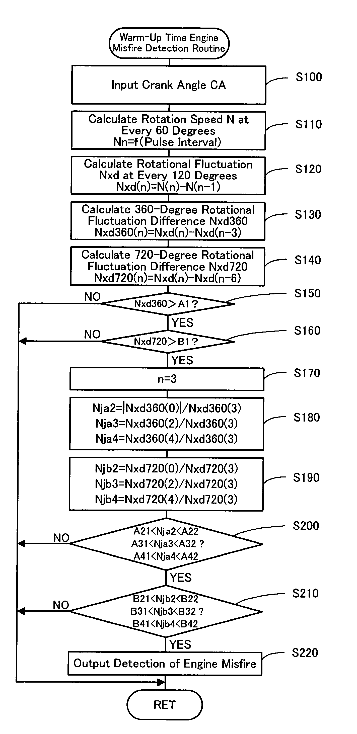
[0039]In the warm-up time engine misfire detection routine of the second embodiment, the CPU 24a of the engine electronic control unit 24 first inputs data required for detection of an engine misfire, for example, the crank angle CA from the crank angle sensor 140 (step S100) and computes the rotation speed N of the crankshaft 26 at the crank angle CA of every 60 degrees, based on the input crank angle CA (step S110). The CPU 24a subsequently calculates the rotational fluctuation Nxd at the crank angle CA of every 120 degrees corresponding to the ignition timing of each of the six cylinders of the engine 22 as the difference of the rotation speed N at the crank angle CA of every 60 degrees (step S120). The CPU 24a then successively computes the difference between the calculated rotational fluctuation Nxd at a certain crank angle CA and the calculated rotational fluctuation Nxd at the 360 degree-prior crank angle CA as the rotational fluctuation difference Nxd360 (step S130) and the ...

first embodiment

[0041]When all of the intermediate rotational fluctuation differences Nm(1) through Nm(4) are less than the preset intermediate misfire reference value C1, the cylinder having the rotational fluctuation differences Nxd360 and Nxd720 respectively exceeding the first 360-degree misfire reference value A1 and the first 720-degree misfire reference value B1 is specified as a misfired cylinder having a third ordinal number of ignition (step S170). In The CPU 24a then calculates the rotational fluctuation difference proportions Nja2, Nja3, and Nja4 (step S180) and the rotational fluctuation difference proportions Njb2, Njb3, and Njb4 (step S190) and detects an engine misfire based on the calculated rotational fluctuation difference proportions Nja2, Nja3, and Nja4 and the calculated rotational fluctuation difference proportions Njb2, Njb3, and Njb4 (steps S200 to S220), in the same manner as the warm-up time engine misfire detection routine of the When any of the intermediate rotational ...


PUM


Abstract

The engine misfire detection apparatus of the invention successively determines whether a rotational fluctuation difference Nxd360 as a difference between a rotational fluctuation Nxd at a certain crank angle CA of an engine and a rotational fluctuation Nxd at a 360 degree-prior crank angle CA exceeds a predetermined reference value A1 (step S150) and whether a rotational fluctuation difference Nxd720 as a difference between the rotational fluctuation Nxd at the certain crank angle CA and a rotational fluctuation Nxd at a 720 degree-prior crank angle CA exceeds a predetermined reference value B1 (step S160). The engine misfire detection apparatus detects a misfire of the engine upon satisfaction of all conditions regarding rotational fluctuation difference proportions Nja2, Nja3, and Nja4 on the basis of the rotational fluctuation difference Nxd360 (step S200) and all conditions regarding rotational fluctuation difference proportions Njb2, Njb3, and Njb4 on the basis of the rotational fluctuation difference Nxd720 (step S210), when both the rotational fluctuation differences Nxd360 and Nxd720 exceed the respective reference values A1 and B1 (steps S150 and S160). This arrangement ensures adequate and accurate detection of an engine misfire during warm-up of a catalyst included in an exhaust emission control unit with a significant delay of the ignition timing in the engine.

Description

TECHNICAL FIELD[0001]The present invention relates to an engine misfire detection apparatus for internal combustion engine and a corresponding engine misfire detection method. More specifically the invention pertains to an engine misfire detection apparatus that detects a misfire in a plural-cylinder internal combustion engine, as well as to a corresponding engine misfire detection method that detects a misfire in the internal combustion engine.BACKGROUND ART[0002]One proposed engine misfire detection apparatus adopts a specific criterion level lower than a standard criterion level for detection of a misfire of an internal combustion engine during warm-up of a catalyst included in an exhaust emission control unit for catalytic conversion of the exhaust emission from the internal combustion engine (see, for example, Patent Document 1). The proposed apparatus detects a misfire of the internal combustion engine during the catalyst warm-up time when an average rotation speed variation o...

Claims


Application Information

Patent Timeline
Patent Type & Authority Patents(United States)
IPC IPC(8): G01M15/00B60K6/445B60W10/06B60W20/00F01N3/20F01N3/24F02D29/02F02D45/00F02P5/15G01M15/04G01M15/06G01M15/11
CPCB60K6/445B60W10/06B60W30/20F02D41/0097F02D41/0245F02D41/1498F02P5/1506G01M15/11B60W20/00F02D2200/1015Y02T10/46Y02T10/54Y02T10/26Y02T10/6239Y02T10/12Y02T10/40Y02T10/62F01N3/20F02D45/00F02P5/15B60W20/50
Inventor AKIMOTO, HIKOKAZUHARADA, OSAMUNISHIGAKI, TAKAHIROKATAYAMA, AKIHIRO
Owner TOYOTA JIDOSHA KK
Why Eureka
Try Eureka