Flow regulating valve, flow rate measuring device, flow control device, and flow rate measuring method

a technology of flow regulating valve and control device, which is applied in the direction of valve operating means/release devices, process and machine control, instruments, etc., can solve the problem of not including means, and achieve the effect of easy attachment and increased detection accuracy

Inactive Publication Date: 2005-06-02
TOYO VALVE
View PDF5 Cites 14 Cited by
  • Summary
  • Abstract
  • Description
  • Claims
  • Application Information

AI Technical Summary

Benefits of technology

[0013] In the present invention, it is preferable that the above-described valve element is constructed to be rotatable around an axis that intersects the above-described flow-channel direction. Where the valve element is constructed to be rotatable around the axis intersecting the flow-channel direction of fluid (in a case of a rotary valve), although the valve opening degree of the valve element changes in compliance with rotations, the above-described stress detecting means is composed so as to detect a flow-channel-direction force component which is not directly influenced by rotations of the valve element, whereby influences due to the opening and closing operations of the valve element are reduced to increase the detection accuracy, and the detecting means can be simply constructed.
[0014] In the present invention, it is preferable that the above-described stress detecting means includes a detector which is able to detect a force, relative displacement or relative strain between the above-described valve element or a member fixed at least in the above-described flow-channel direction with respect to the above-described valve element and a housing which rotatably and axially supports the above-described valve element or a member fixed at least in the flow-channel direction with respect to the corresponding housing. Such a detector can be easily attached by only slightly modifying the conventional valve structure, wherein the structure of the valve is not unnecessarily complicated. In this case, a portion detected by the detector is not only at the valve element but also the valve rod or axial supporting portion which supports the valve element. In particular, it is preferable, in view of a lowering in the influence resulting from opening and closing operations of the valve element, that a detecting portion is established at a portion that does not move along with the opening and closing operations of the valve element and is fixed in the flow-channel direction with respect to the valve element (for example, an axially supporting portion, etc., that does not rotate along with the valve element in a rotary valve and is rotatably coupled with respect to the valve element).

Problems solved by technology

However, it does not include a means that detects a torque in the rotation direction of the valve, element.

Method used


Image

  • Flow regulating valve, flow rate measuring device, flow control device, and flow rate measuring method
  • Flow regulating valve, flow rate measuring device, flow control device, and flow rate measuring method
  • Flow regulating valve, flow rate measuring device, flow control device, and flow rate measuring method

Examples


Embodiment Construction

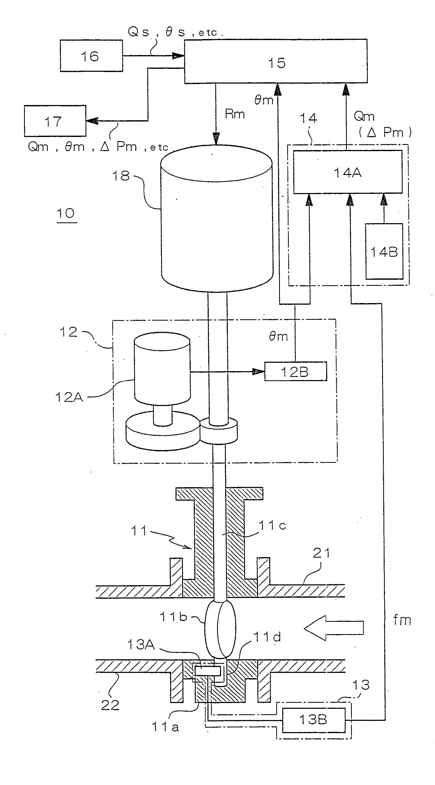
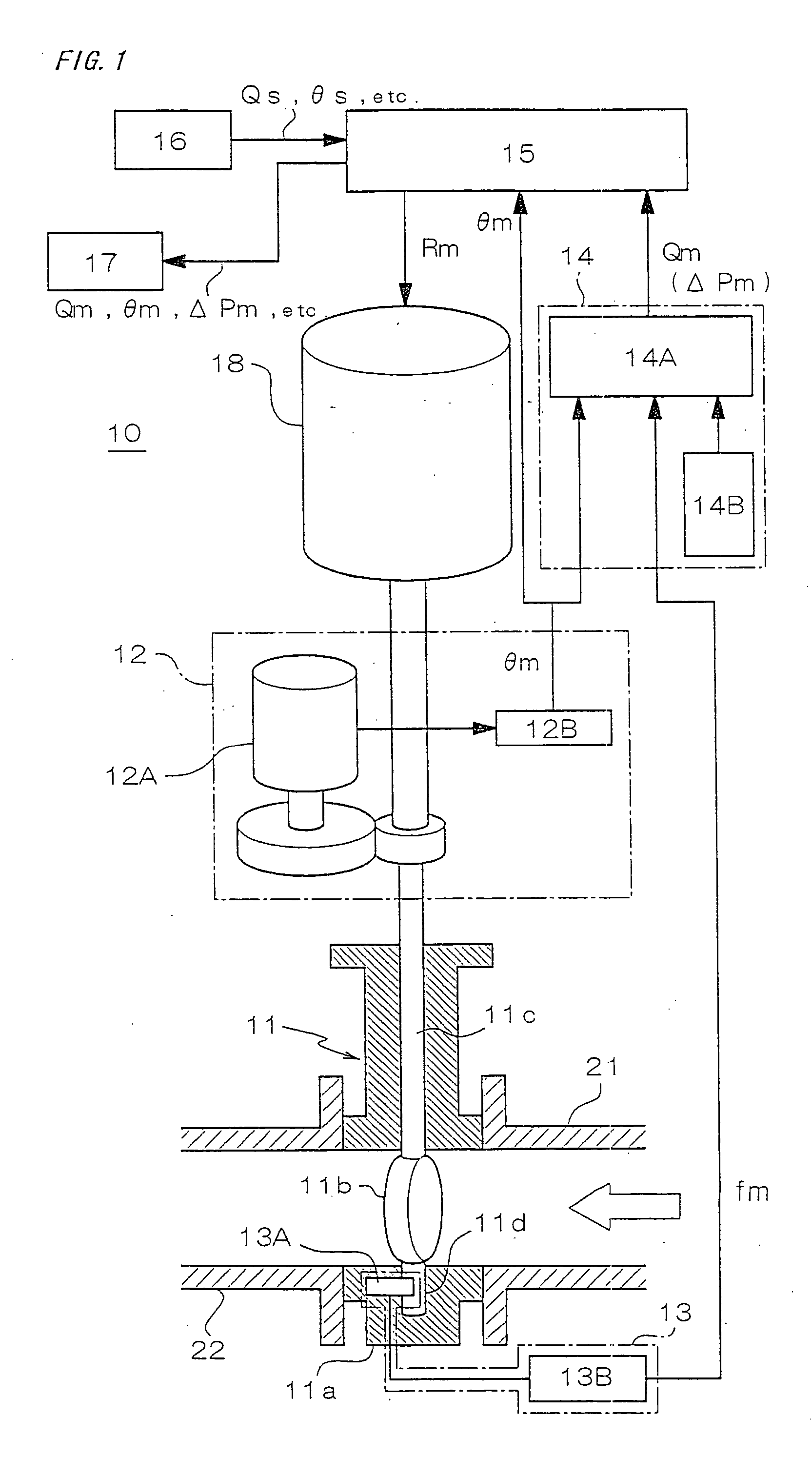
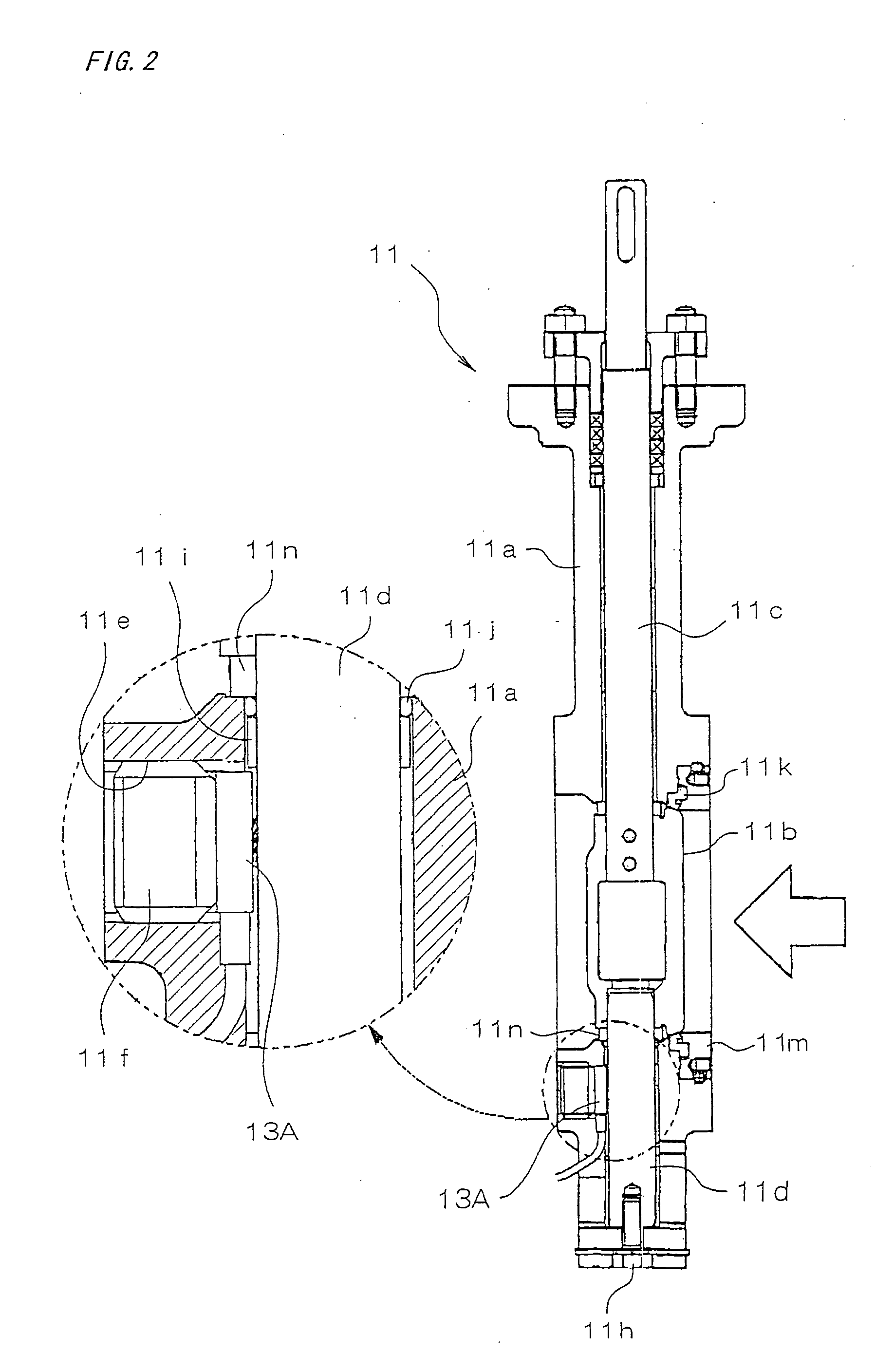
[0032] Next, a detailed description is given of embodiments of a flow regulating valve, a flow rate measuring device, a flow control device, and a flow rate measuring method according to the invention with reference to the accompanying drawings. The “flow regulating valve” referred to in the present invention is based on a functional concept and resultantly includes all valves having a structure which is capable of regulating the flow rate. Therefore, the flow regulating valve is not limited to valves which are generally used for the purpose of regulating the flow rate.

[0033] Where the present invention is carried out, a low-channel-direction force component (hereinafter merely called a “stress”) of a load applied to a valve element of a flow regulating valve by a fluid is detected. Detection of the stress may be based on a method in which a detector directly detects the stress applied to the valve element, and a method for obtaining a value corresponding to the above-described str...


PUM


Abstract

A flow regulating valve (11), which has a valve disk (11b) operably disposed in a flow channel and is capable of regulating the flow of fluid according to the valve opening degree of the valve disk (11b), is characterized by comprising a stress detecting means (13) for detecting the flow-channel-direction force component of a load applied to the valve disk by the fluid, and a valve opening degree detecting means (12) for detecting the degree of opening of the valve disk. The flow rate calculating means (14) finds the flow rate (Qm) from the stress (fm) obtained from the stress detecting means and from the valve opening degree (θm) obtained from the valve opening degree detecting means. A control means (15) controls a valve disk driving means (18) on the basis of the flow rate to drive the valve disk for opening and closing. This makes it possible to find the flow rate with higher sensitivity and accuracy than in the prior art, the construction being compact and simple, providing stabilized data.

Description

TECHNICAL FIELD [0001] The present invention relates to a flow regulating valve, a flow rate measuring device, a flow control device, and a flow rate measuring method, in particular to a flow rate measuring technique or a flow rate controlling technique, which is preferred where a butterfly valve is used. BACKGROUND ART [0002] Generally, a butterfly valve has been known in which a plate-shaped valve element rotating around an axis roughly orthogonal to the flow-channel direction is rotatably composed with respect to the housing thereof. The butterfly valve is constructed so that it can control its flow rate by the valve opening degree of the valve element. [0003] A method for measuring a flow rate and a method for controlling the flow rate, for which such a butterfly valve is utilized, are described in Japanese Unexamined Patent Publication No. Hei-7-174596. In the publication, it is described that the dynamic torque of the valve element of the butterfly valve is detected, and the f...

Claims


Application Information

Patent Timeline
Patent Type & Authority Applications(United States)
IPC IPC(8): G01F1/00G01F1/26G01F1/28G01F1/42G05D7/06
CPCG01F1/26G05D7/0635G01F1/28Y10T137/7759G05D7/06
Inventor TANAKA, TOSHIHARUICHINOSE, TADAHARUYATA, KATSUHISA
Owner TOYO VALVE
Why Eureka
Try Eureka