Laser radar apparatus

a radar and laser technology, applied in the field of laser radar apparatus, can solve the problems of large loss of light reception, low reflectivity of fog and the like, and cannot be detected, so as to increase the distance to and from the detecting unit, increase the light reception amount, and strong light intensity

Active Publication Date: 2016-07-21
DENSO WAVE INC
View PDF0 Cites 10 Cited by
  • Summary
  • Abstract
  • Description
  • Claims
  • Application Information

AI Technical Summary

Benefits of technology

[0022]Therefore, according to the first aspect, of outgoing laser light emitted with the initial small divergence angle for long-distance detection, the outgoing laser light reflected by the flat reflective surface is emitted towards the direction of a detection area with the initial small divergence angle. The outgoing laser light has a small divergence angle for long-distance detection. Therefore, the light intensity becomes higher towards the portion near the optical axis and becomes lower towards the end portion far from the optical axis. Of the outgoing laser light, the optical axis portion (the center portion having a high light intensity) is reflected without being diffused by the flat reflective surface and has a strong light intensity. Therefore, the optical axis portion reaches a far distance. Consequently, the optical axis portion is reflected with sufficient light intensity by a target that is at a far distance. In this case, the laser light travels out and back over a long distance. Therefore, regardless of the initial divergence angle being small, the laser light spreads to an extent amounting to the projection area of the reflective surface of the rotating mirror. Consequently, light reception loss of the returning laser light at the rotating mirror is also small. As a result, the detecting unit can detect a distant object with sufficient light reception amount.
[0023]Meanwhile, of the outgoing laser light, the outgoing laser light in the end portion (peripheral portion) that has a low light intensity is reflected by the sloped reflective surface, and is spread (diffused) to the periphery of the optical axis of the outgoing laser light emitted from the flat reflective surface. Therefore, when reflected by an object at a near distance, the outgoing laser light is received by substantially the overall surface of the rotating mirror and is reflected towards the direction of the detecting unit by substantially the overall surface of the reflection mirror for light reception. Moreover, while the outgoing laser light reflected by the sloped reflective surface has a low light intensity, when the outgoing laser light reflected by an object at a near distance returns to the detecting unit, the outgoing laser light maintains the light intensity to an extent that light reception can be sufficiently detected by the detecting unit because the distance to and from the object is short.
[0024]As described above, regarding an object at a near distance, the above-described diffused outgoing laser light is reflected while maintaining a light intensity that is sufficient for detection. The outgoing laser light is incident on the overall rotating mirror and is received by a wide area of the reflection mirror for light reception. Therefore, even when a portion of the returning laser light passes through the hole in the reflection mirror for light reception, overall, the light reception amount at the detecting unit increases. As a result, light reception capability for near distances can be improved.
[0025]In addition, according to a second aspect of the laser radar apparatus, the rotating mirror (20) includes a flat reflective surface (20A1) that forms a flat planar shape in a center portion of the reflective area (E) that reflects the outgoing laser light (6a), and includes a sloped reflective surface (20A2) in a peripheral portion of the center portion of the reflective area (E), the sloped reflective surface (20A2) spreading the outgoing laser light (6a) incident on the peripheral portion to a periphery of an optical axis (La1) of the outgoing laser light (6a) emitted from the flat reflective surface (20A1), after intersecting with the optical axis (La1). According to the second aspect, effects similar to those of the first aspect are achieved.

Problems solved by technology

As a result, fog and the like that have low reflectivity are not detected.
Therefore, light reception loss is large.

Method used


Image

  • Laser radar apparatus
  • Laser radar apparatus
  • Laser radar apparatus

Examples


first embodiment

[0039]A first embodiment of the present invention will be described with reference to FIG. 6 to FIG. 8.

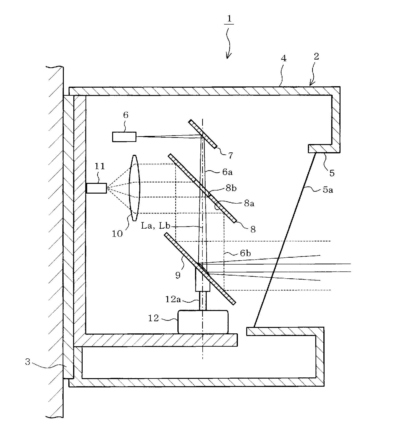
[0040]As shown in FIG. 6, a laser radar apparatus 1 according to the first embodiment includes an apparatus main body 2. The apparatus main body 2 has a main body base 3 and an apparatus case 4. A laser-light irradiation opening 5 is formed in the apparatus case 4. The laser light radiation opening 5 is provided with a cover 5a that is integrated with or separate from the apparatus case 4. The cover 5a is capable of transmitting laser light.

[0041]Furthermore, a laser light emitting unit 6 that emits laser light, a reflection mirror for emission 7, a reflection mirror for light reception 8, a rotating mirror 9 used for both expansion of outgoing light and light reception, a detecting unit 11 that receives, through a light reception lens 10, laser light reflected by an object, and a motor 12 that rotates the rotating mirror 9 are provided inside the apparatus case 4.

[0042]The laser l...

second embodiment

[0058]FIG. 10 shows a second embodiment. A rotating mirror 20 differs from the rotating mirror 9 according to the first embodiment. Other configurations are similar to those according to the first embodiment.

[0059]In the rotating mirror 20, a flat reflective surface 20A1 that is formed into a flat planar shape is formed in a center portion of a reflective area E that reflects the outgoing light 6a. A sloped reflective surface 20A2 is formed in a peripheral portion of the center portion. The sloped reflective surface 20A2 configures a sloped form that makes the outgoing light 6a incident on the sloped reflective surface 20A2 spread to the periphery of an optical axis La1 of the outgoing light 6a emitted from the flat reflective surface 20A1, after intersecting with the optical axis La1. In addition, on a reflective surface 20A of the rotating mirror 20, an area further towards the outer side than the reflective area E functions as a light receiving surface 20A3 for the reflected ligh...


PUM


Abstract

A laser radar apparatus that includes a rotating mirror is provided. The rotating mirror has a reflective area that reflects outgoing laser light. A flat reflective surface that forms a flat planar shape is formed in a center portion of the reflective area. A sloped reflective surface is formed in a peripheral portion of the center portion of the reflective area, the sloped reflective surface spreading the outgoing laser light incident on the peripheral portion to a periphery of an optical axis of outgoing laser light emitted from the flat reflective surface.

Description

CROSS-REFERENCE TO RELATED APPLICATION[0001]This application is based on and claims the benefit of priority from earlier Japanese Patent Application No. 2013-194171 filed Sep. 19, 2013, the description of which is incorporated herein by reference.BACKGROUND[0002]1. Technical Field[0003]The present invention relates to a laser radar apparatus that detects the presence, orientation, distance, and the like of an object using laser light.[0004]2. Background Art[0005]A laser radar apparatus is used as an apparatus that uses laser light to detect the presence and orientation, as well as distance and the like, of an object in a detection area to be targeted. In general, in the laser radar apparatus, laser light (outgoing light) emitted from a laser light emitting unit is reflected towards the direction of the detection area by a rotating mirror and is scanned in accompaniment with the rotation of the rotating mirror. In addition, laser light (returning light) that has been reflected to an ...

Claims


Application Information

Patent Timeline
Patent Type & Authority Applications(United States)
IPC IPC(8): G01S17/42G01S7/481
CPCG01S7/4817G01S17/42G01S7/4816
Inventor SAKABE, KOUJI
Owner DENSO WAVE INC
Why Eureka
Try Eureka