System and method for controlling a state of charge of an energy storage system

a technology of energy storage system and state of charge, which is applied in the direction of engine-driven generators, process and machine control, electric devices, etc., can solve the problems of reducing the range in which the target soc resides, and the relative long life of the target soc, so as to reduce the target soc, the effect of reducing the target so

Inactive Publication Date: 2010-02-09
FORD GLOBAL TECH LLC
View PDF11 Cites 19 Cited by
  • Summary
  • Abstract
  • Description
  • Claims
  • Application Information

AI Technical Summary

Benefits of technology

[0010]In addition to the foregoing, a driver may be known to brake very quickly. In such a case, less regenerative braking energy may be captured than if the driver braked more slowly. Again, it may be beneficial to maintain a target SOC above a baseline target SOC, since it will be contemplated that less regenerative braking energy will be available to charge the battery. Driving habits such as these can be stored, for example, in a vehicle system controller, which may also maintain information about seat positions or other particulars of a driver. Communication with the controller as to which driver is operating the vehicle can be facilitated, for example, by actuating a button on a key fob when the driver opens the vehicle.
[0011]The expected life span of an energy storage system, such as a battery, may be dependent on a number of factors, including how the system is operated. For example, if a battery is operated such that the state of charge is maintained over a relatively narrow range, it may have a relatively long life. Conversely, a battery that is operated such that the SOC is allowed vary significantly within a wide range of states of charge may have a shorter life span. How the battery is operated is typically a decision for the original equipment manufacturer (OEM) of the vehicle. For example, if the OEM wishes to increase the life span of the battery, it may decrease the range in which the target SOC resides.
[0012]Although the expected life span of the battery may be improved by such operation, the engine will likely operate more frequently, since the configuration will allow little variation in the operating SOC. Thus, the present invention provides a system and method for adjusting the range in which the target SOC resides in order to provide an expected life span for the battery desired by the vehicle owner. If, for example, the vehicle owner desires a greater life span for the battery, the range in which the target SOC resides can be set to be relatively narrow. Conversely, if the owner desires greater fuel economy and lower emissions, the range can be increased.
[0015]Similarly, if the temperature of the ambient air outside the vehicle is such that use of a maximum air conditioning setting is contemplated, the target battery SOC may be reduced, since it is expected that the engine will be forced on when the air conditioning is activated. Other systems may also force the engine on, depending on how the HEV control system is configured. For example, if the vehicle headlights are turned on when other electrical systems are in use, the added electrical load of the headlights may cause the engine to be operated. This could occur even if the battery SOC is relatively high and the engine would not otherwise be started. The present invention, therefore, includes a system and method for reducing the target SOC when there are heavy electrical loads, or when such loads are anticipated—for example, when there are electrical systems in use, and an ambient light sensor detects that the use of the headlights is expected.
[0018]In addition, a driver may input a distance until a driving cycle is complete—i.e., how many miles until a destination is reached and the vehicle shut off. If the distance is above some predetermined distance, the target SOC can be decreased, since there will be ample opportunity to recharge the battery prior to the destination being reached. Conversely, if the destination distance is below the predetermined distance, the target SOC may be adjusted upward to ensure that there is ample battery charge when the vehicle is shut off. This helps to ensure that there will always be battery power available to start the vehicle.

Problems solved by technology

For example, if a battery is operated such that the state of charge is maintained over a relatively narrow range, it may have a relatively long life.
For example, if the OEM wishes to increase the life span of the battery, it may decrease the range in which the target SOC resides.

Method used


Image

  • System and method for controlling a state of charge of an energy storage system
  • System and method for controlling a state of charge of an energy storage system
  • System and method for controlling a state of charge of an energy storage system

Examples


Embodiment Construction

)

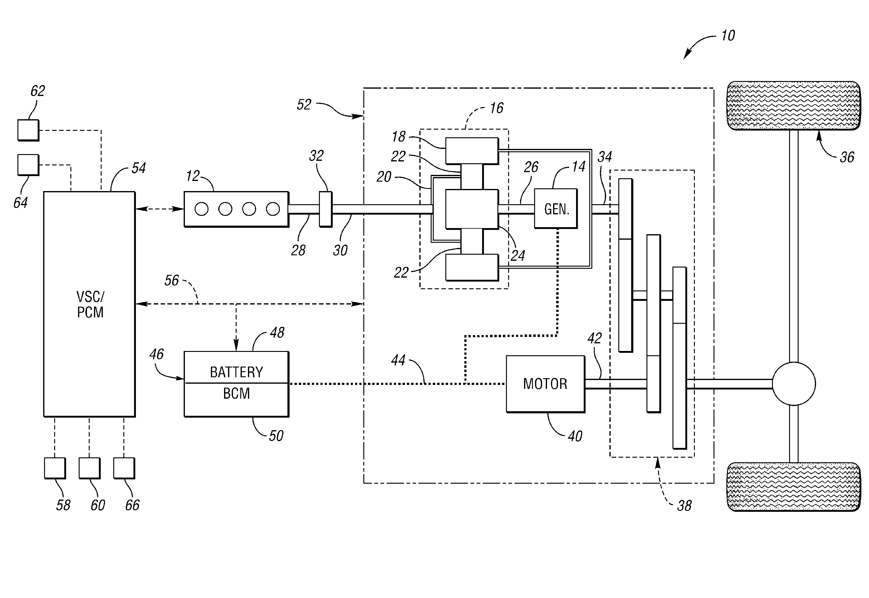
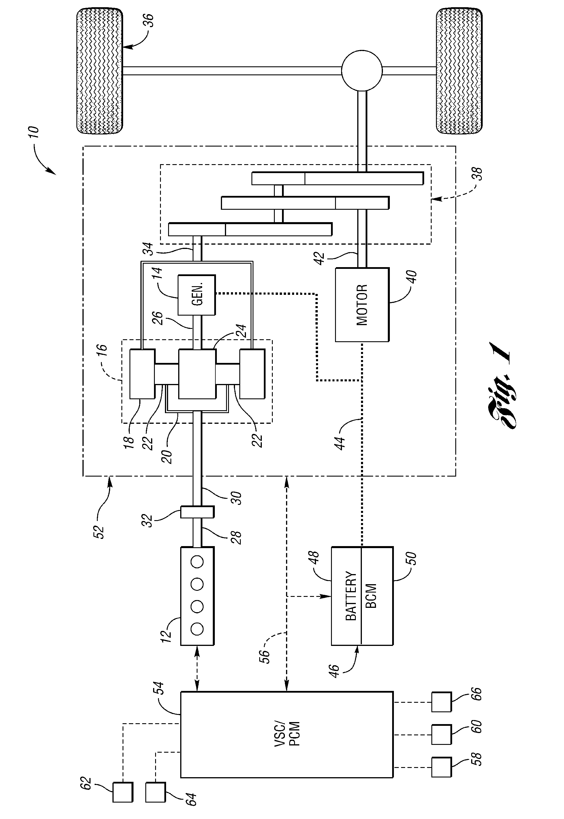
[0024]FIG. 1 shows a schematic representation of a vehicle 10, which includes an engine 12 and an electric machine, or generator 14. The engine 12 and the generator 14 are connected through a power transfer arrangement, which in this embodiment, is a planetary gear arrangement 16. Of course, other types of power transfer arrangements, including other gear sets and transmissions, may be used to connect the engine 12 to the generator 14. The planetary gear arrangement 16 includes a ring gear 18, a carrier 20, planet gears 22, and a sun gear 24.

[0025]The generator 14 can also be used as a motor, outputting torque to a shaft 26 connected to the sun gear 24. Similarly, the engine 12 outputs torque to a crankshaft 28, which is connected to a shaft 30 through a passive clutch 32. The clutch 32 provides protection against over-torque conditions. The shaft 30 is connected to the carrier 20 of the planetary gear arrangement 16, and the ring gear 18 is connected to a shaft 34, which is connec...


PUM


Abstract

A system and method for controlling the state of charge of an energy storage system examines a number of parameters to determine if a target state of charge should be adjusted. Parameters related to one or more of: a target life span of the energy storage system, driving habits of a vehicle operator, or environmental conditions are examined. The target state of charge is changed from a predetermined baseline target state of charge when the parameter values meet predetermined conditions.

Description

BACKGROUND OF THE INVENTION[0001]1. Field of the Invention[0002]The present invention relates to a system and method for controlling a state of charge for an energy storage system.[0003]2. Background Art[0004]With the ever increasing need to produce vehicles that are more fuel efficient, hybrid electric vehicles (HEV's) have provided an improvement in fuel economy over many conventional vehicles that utilize only an internal combustion engine to drive the vehicle. One of the primary advantages of an HEV is that it allows the vehicle to be powered by one or more electric motors under certain operating conditions. For example, if the speed of the vehicle is relatively moderate, and the battery or other electrical power sources sufficiently charged, the engine may be shut off, and the vehicle powered exclusively by the electric motors. As operating conditions change, the engine may be started to provide additional power, and if needed, operate a generator to charge the battery.[0005]In...

Claims


Application Information

Patent Timeline
Patent Type & Authority Patents(United States)
IPC IPC(8): H02J7/00
CPCB60K6/365B60W20/10B60L3/0046B60L7/14B60L11/123B60L11/14B60L11/1859B60L11/1862B60W10/08B60W10/26H02J7/1446B60K6/445B60L2240/662B60L2240/80B60W20/00B60W2510/244B60W2510/248B60W2540/30B60W2550/12B60W2550/402Y02T10/6217Y02T10/7005Y02T10/7044Y02T10/705Y02T10/7077Y02T10/7291Y02T10/92Y02T90/16Y02T10/6239B60L50/16B60L50/61B60L58/14B60W2555/20B60W2556/50Y02T10/62Y02T10/70Y02T10/7072Y02T10/72
Inventor ELDER, RONALDSCHONDORF, STEVEN
Owner FORD GLOBAL TECH LLC
Why Eureka
Try Eureka