Plunger drive with load profile adaptation

a technology of servo motors and load profiles, which is applied in the direction of presses, press rams, manufacturing tools, etc., can solve the problems of increased load, additional load for servo motors, and elastic deformation of presses, so as to reduce the thermal load of servomotors, reduce the effective torque, and reduce the thermal load

Inactive Publication Date: 2015-08-25
SCHULER PRESSEN GMBH & CO KG
View PDF14 Cites 2 Cited by
  • Summary
  • Abstract
  • Description
  • Claims
  • Application Information

AI Technical Summary

Benefits of technology

[0010]The load relief of the servo drive results in particular in a reduction of the effective torque and, in this way, in a load reduction of the one or several servomotors which drive the plunger. The servomotors need to convert less braking energy which reduces the thermal load of the servomotors. The load relief can be utilized by using possibly smaller servomotors than would otherwise be necessary. Also the energy to be converted in the transverter can be reduced. In addition the energy to be retransmitted to the electric power supply or the intermediate storage device can be reduced whereby the intermediate storage device, if present, can be smaller and power supply load variations can be reduced.
[0011]It is possible to eliminate the counterforce to be applied by the servo drive for braking the upward movement of the plunger after passing the bottom dead center or to control it to a value other than zero. This value maybe a predetermined constant value. But it can also be determined to be guide angle or time-dependent. In this way, smooth operational transitions between the position-controlled operation and the force-controlled operation of the servomotor are possible. This operational transition preferably concerns all the servomotors forming the servo drive or at least the otherwise position controlled servomotors at this same time.

Problems solved by technology

Between the plunger and a press table, that is driving the transformation of a work piece, generally substantial forces are effective which result in an elastic deformation of the press when the plunger reaches the lower dead center position.
This is an additional load for the servo drives.
Such equipment is effective over a relatively long distance and result in the above-mentioned increased load.

Method used


Image

  • Plunger drive with load profile adaptation
  • Plunger drive with load profile adaptation
  • Plunger drive with load profile adaptation

Examples


Embodiment Construction

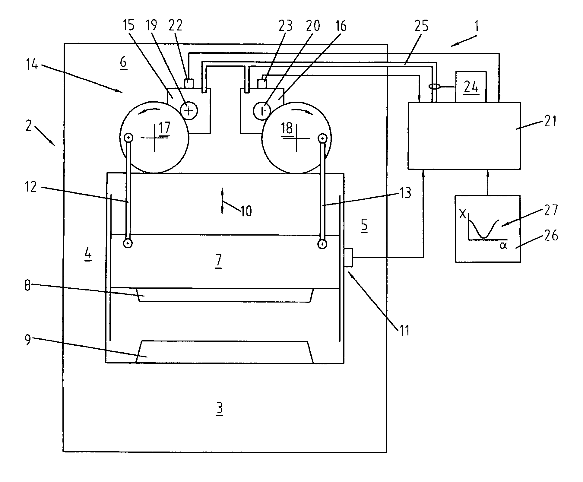
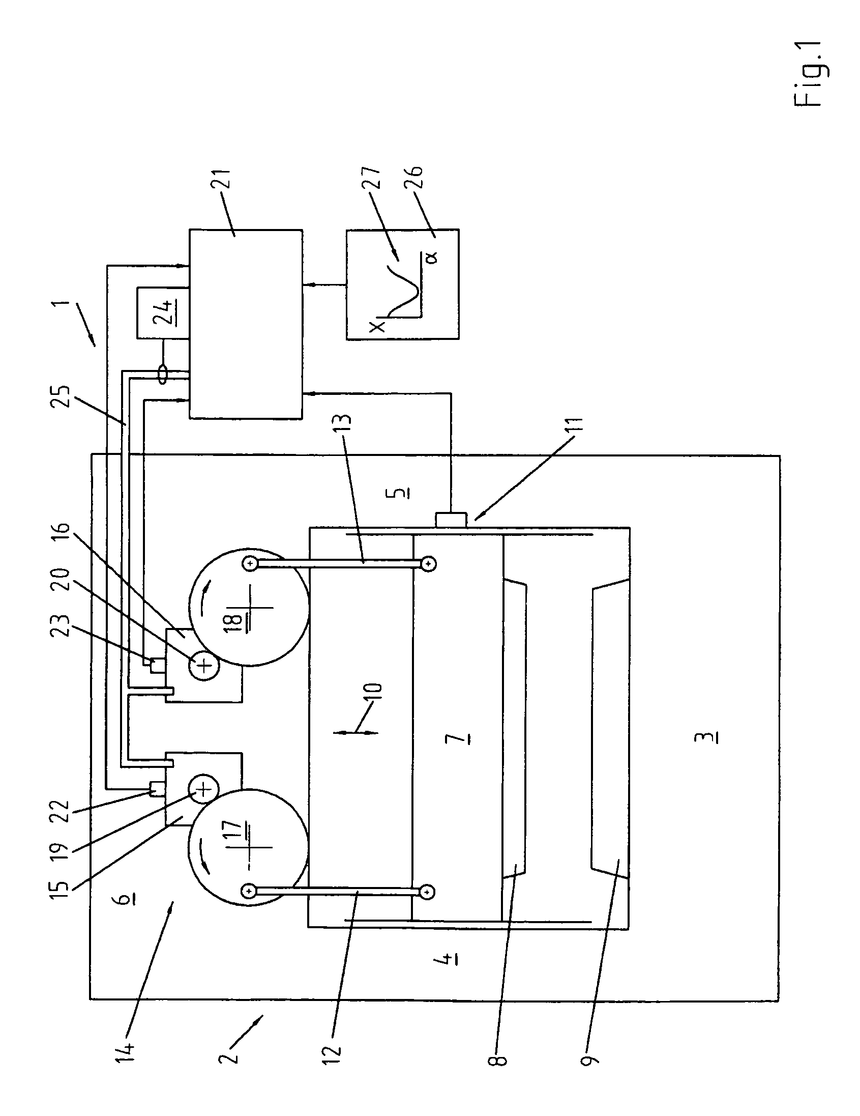
[0017]In FIG. 1 a servo press 1 is schematically shown in an abstract manner and limited to a few components. The servo press I comprises a press frame 2 which includes, for example, a press table 3, a press stand 4, 5, and a top part 6. On the press frame 2, a plunger 7 may be movably supported. In the exemplary embodiment, the plunger 7 is arranged above the press table 3 and is movable vertically preferably along a linear line up and down. The plunger 7 carries a top tool 8. The press table carries the corresponding bottom tool 9. The movement of the plunger 7 in the direction of the arrow 10 is defined as the X-direction. For detecting the plunger movement, optionally, an X-position sensor 11 may be provided.

[0018]The plunger 7 may be connected via suitable drive means, for example, two connecting rods 12, 13, to a servo drive 14 which is arranged, for example, in the top part 6. The servo drive comprises, for example, one or several servomotors 15, 16 which are suitable for dri...


PUM


Abstract

A method of operating a servo press and apparatus therefore, including a press plunger and a servo drive and such a press, the press plunger is operated in accordance with a predetermined guide angle / position-curve based on a guide angle α and the movement of the plunger is controlled in accordance with this curve with a tolerance which depends on the guide angle α.

Description

CROSS-REFERENCE TO RELATED APPLICATION[0001]This application claims the priority benefits of German Application No. 10 2009 057 409.3 filed Dec. 8, 2009.BACKGROUND OF THE INVENTION[0002]The invention resides in a method for operating a servo press and in a press equipped with a servo drive.[0003]For the transformation of massive metal components as well as for the deformation of metal sheets increasingly presses are used whose plungers are driven preferably by an electric servo drive. In this respect, DE 10 2006 033 562 B3 discloses presses whose plungers are driven by servomotors. The servomotors provide for the respective plungers an up and down stroke movement in accordance with a predetermined guide angle / position-curve. With the programmable control of the servomotors guide angle / position-curves can be achieved which to a large extent or even precisely approximate curves as they were generated in the past by mechanical presses. Also novel curves which can not be realized with m...

Claims


Application Information

Patent Timeline
Patent Type & Authority Patents(United States)
IPC IPC(8): B30B15/14B30B15/00B30B1/26
CPCB30B15/0094B30B1/26B30B15/148
Inventor SCHMEINK, MARTIN
Owner SCHULER PRESSEN GMBH & CO KG
Why Eureka
Try Eureka