Pneumatic emergency brake assurance module

a technology of pneumatic emergency brake and assurance module, which is applied in the direction of braking system, braking components, transportation and packaging, etc., can solve the problems of wheel slide and wheel lockup with extended stopping distance, and the use of electronic hardware safety timers is not sufficient to protect against extended periods of brake reduction without sufficient brake application periods

Active Publication Date: 2010-02-16
WABTEC HLDG CORP
View PDF15 Cites 3 Cited by
  • Summary
  • Abstract
  • Description
  • Claims
  • Application Information

AI Technical Summary

Problems solved by technology

See U.S. Pat. No. 5,735,579 entitled “Brake Assurance Module.” Depending on the configuration of the pneumatic brake components and wheel slip control components, often the use of an electronic hardware safety timer is insufficient for protecting against extended periods of brake reductions without sufficient periods of brake application.
Inhibiting wheel slip control often results in wheel slides and wheel lockups with extended stopping distances.

Method used


Image

  • Pneumatic emergency brake assurance module
  • Pneumatic emergency brake assurance module
  • Pneumatic emergency brake assurance module

Examples


Embodiment Construction

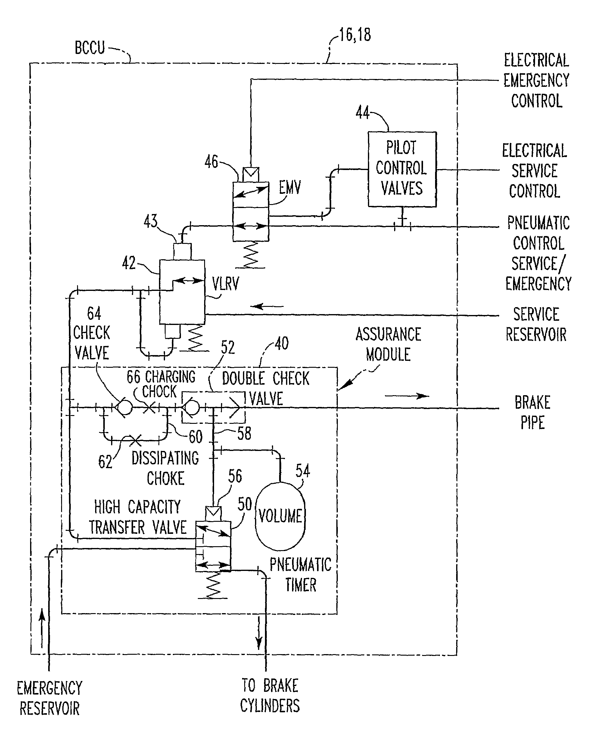
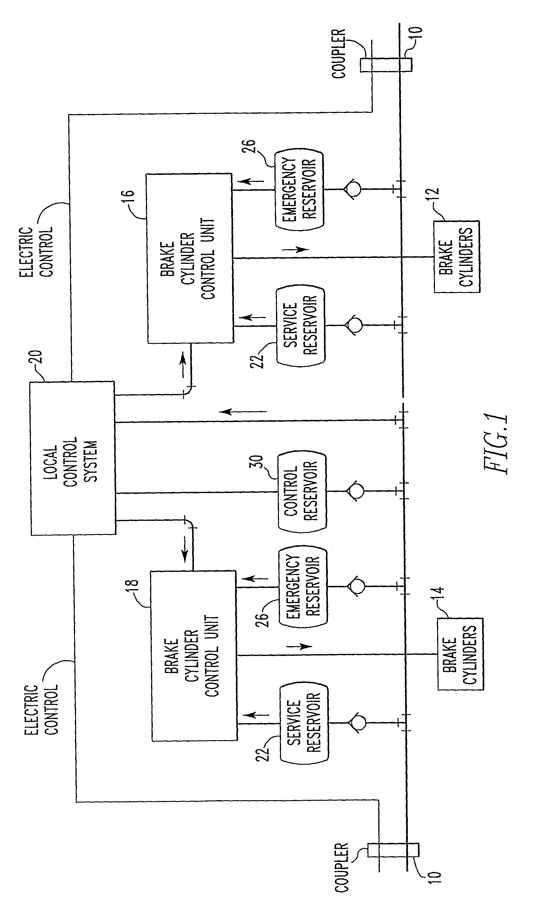
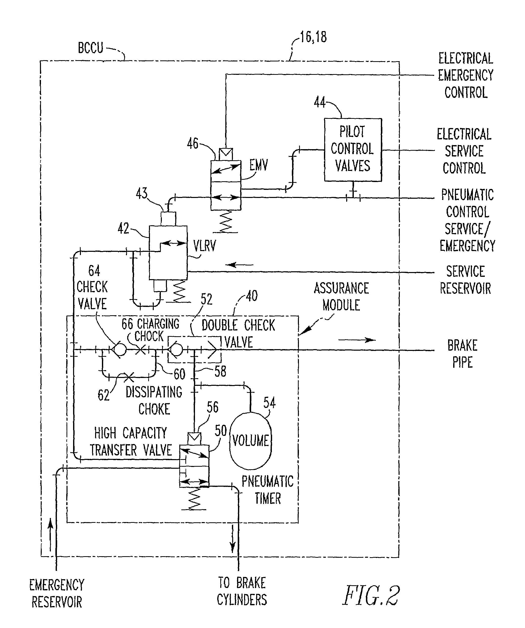
[0020]Referring now to FIG. 1, the transit vehicle has a coupler 10 at each end that mechanically couples adjacent vehicles and provides coupling of the brake pipe and electrical train lines. The brake pipe may be a source of pneumatic pressure for implementing braking. It is used to provide pneumatically transferred signals to the braking systems along the train. The brake pipe, along with the electric train line, implements the combined electrical and pneumatic (electro-pneumatic) braking control.

[0021]As shown in FIG. 1, the transit vehicle has two sets of brake cylinders 12, 14, one for each bogie, for actuating brakes, such as disc brakes, associated with each wheel axle. Each set of brake cylinders is controlled by a Brake Cylinder Control Unit (BCCU) 16, 18. The BCCUs respond to service braking commands and emergency braking commands generated by a local control system 20 which, in some implementations, are functions of a friction brake control unit and a brake pipe control u...


PUM


Abstract

A pneumatic emergency brake assurance module comprises a high capacity transfer valve connected in a first position to the output of the variable load relay valve and in a second position connected to a source of emergency braking air pressure. A timing reservoir is in communication with the pilot port of the high capacity transfer valve. A check valve / choke circuit provides parallel connections between a double check valve and the output of the variable load relay valve such that flow from the variable load relay valve passes through a charging choke and opposite flow to the variable load relay valves passes through a dissipation choke.

Description

BACKGROUND OF THE INVENTION[0001]1. Field of the Invention[0002]It is well known in the brake control art that modern train brake control systems typically use a central controller unit to control the brakes of the rail vehicles that comprise the train. A train operator located in the lead locomotive manipulates the brake handles or like devices of the train to apply and release the brakes of the trucks or bogies on each rail vehicle as desired. The inputs from the brake handles are typically processed by a cab control unit and passed to the central controller unit. In response to these and other inputs, the central controller unit issues a brake command signal along a train line to each of the rail vehicles in the form of either a pneumatic signal or an electrical signal or even both. Brake equipment on each of the rail vehicles applies or releases the brakes according to the dictates of the particular brake command signal received. The central controller unit sends the brake comma...

Claims


Application Information

Patent Timeline
Patent Type & Authority Patents(United States)
IPC IPC(8): B60T8/34
CPCB60T17/228B60T13/683
Inventor WOOD, JAMES A.SCHARPF, ROBERT N.SCHWEIKERT, DAVID E.
Owner WABTEC HLDG CORP
Why Eureka
Try Eureka