
Column pipe catch tool

a technology of column pipe and tool, which is applied in the direction of drilling pipe, borehole/well accessories, load-engaging elements, etc., can solve the problem of difficulty for operators to grasp and retrieve the column pip

Active Publication Date: 2010-02-23
NEWTON PAUL A
View PDF9 Cites 9 Cited by
  • Summary
  • Abstract
  • Description
  • Claims
  • Application Information

AI Technical Summary

Benefits of technology

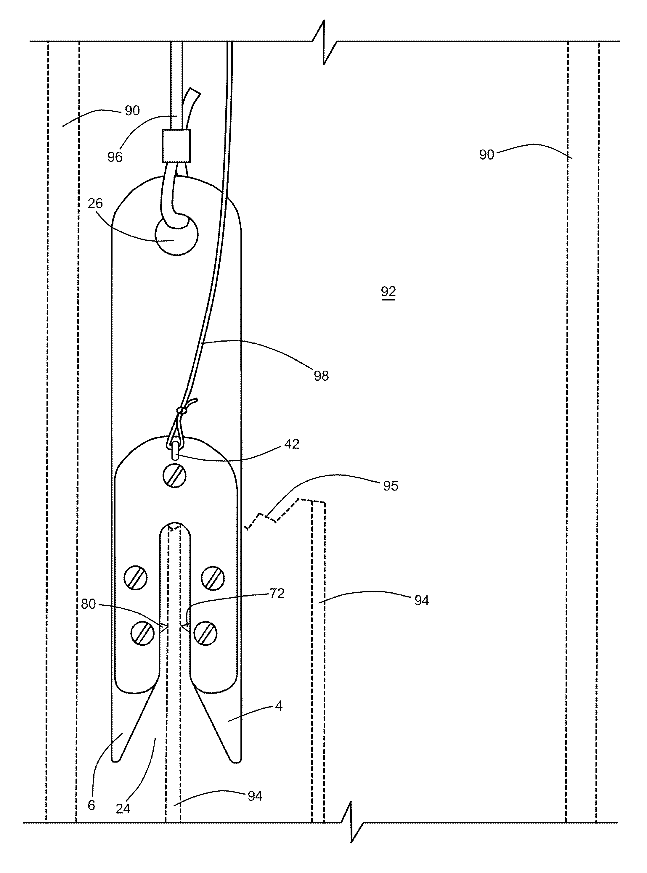
[0009]In use of the instant inventive catch tool, and assuming that a water well column pipe has become fractured or separated at a subterranean level substantially below the well's opening, a sturdy rope is preferably tied to an upper end of the first sub-fork component of the inventive tool. Thereafter, the catch tool is lowered by the rope into the well bore until the lower end of the tool reaches the level of the opening of the column pipe. Upon further lowering of the tool, the column pipe's upper edge or opening may extend upwardly into the pipe wall receiving space between the fork's tines. Repeated attempts at slightly raising and lowering the tool at and about the level of the column pipe's upper opening may be needed in order to cause such upward extension to occur. During the tines' receipt of the pipe wall, the fork's pivot arm c

Problems solved by technology

Such breakage or disconnection undesirably strands a length of column pipe, and often strands an attached submersible electric water pump at the bottom of the well.
In many cases, the upper end of such broken or disconnected well column pipe lies at an elevation several feet below the upper opening of the well casing, making it very difficult for an operator to grasp and retrieve the well column pipe.

Method used


Image

  • Column pipe catch tool
  • Column pipe catch tool
  • Column pipe catch tool

Examples


Embodiment Construction

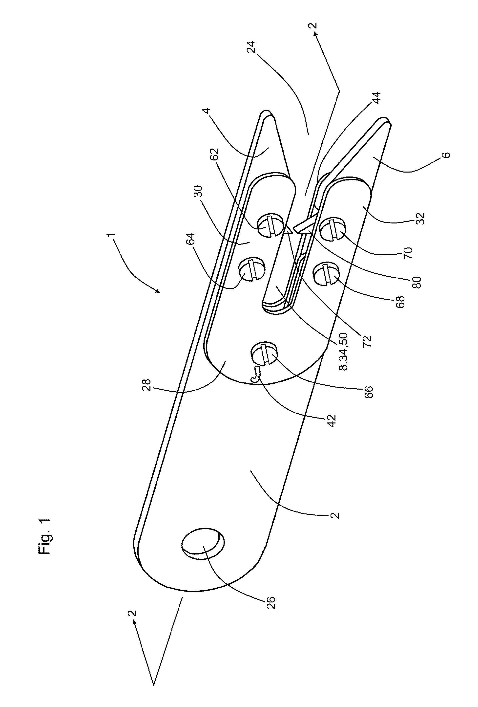
[0020]Referring now to the drawings, and in particular to FIG. 1, the instant inventive well column pipe catch tool is referred to generally by Reference Arrow 1. A major structural component of the catch tool 1 comprises a fork having a pair of tines, the tines forming a flared lower opening 24.

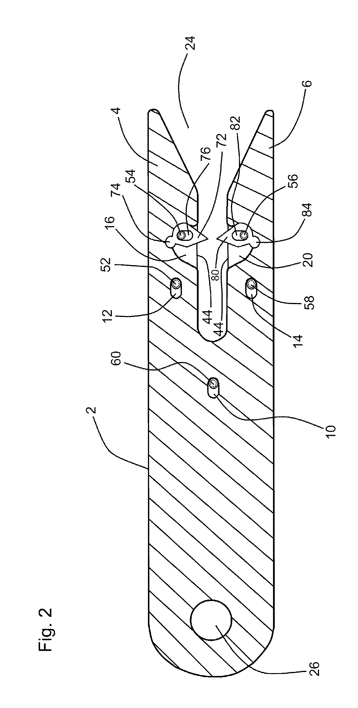
[0021]The fork preferably comprises a stratification of plates including a first sub-fork or interstitial plate 2 having a pair of downwardly extending tines 4 and 6, a second sub-fork or cover plate 28 having a pair of downwardly extending tines 30 and 32, and (referring further simultaneously to FIG. 6) a third sub-fork or cover plate 44 having a pair of downwardly extending tines 46 and 48. Said sub-forks' downwardly extending tines 4, 6, 30, 32, 46, 48, together and in combination form a downwardly opening pipe wall receiving space 8,34,50, such space serving as a pipe wall receiving throat. Referring further simultaneously to FIG. 8, the pipe wall receiving space 8,34,50 is sized and fi...


PUM


Abstract

A catch tool for retrieval of a well column pipe having a pipe wall, the catch tool incorporating a fork having a pair of spaced tines; and a pair of clamping pivot arms connected operatively to the fork, the clamping arms being adapted for, upon the receipt by the tines of the pipe wall, grasping the pipe wall; the clamping arms having proximal and distal ends, the arms being adapted for pivoting movements between first and second positions, the arms' distal ends being displaced away from each other a distance less than the pipe wall's thickness dimension while in the first position, and being carried by the pipe wall to their second positions.

Description

FIELD OF THE INVENTION[0001]This invention relates to apparatus, mechanism, and assemblies utilized in water well construction, restoration, and maintenance. More particularly, this invention relates to such apparatus, assemblies, and mechanisms which are specially adapted for retrieving broken or disconnected column pipes which may upon occasion reside within such wells.BACKGROUND OF THE INVENTION[0002]In the water well construction, repair, and maintenance art, it is known that water well's column pipe may upon occasion break or disconnect at a joint at a subterranean location within the well's bore. Such breakage or disconnection undesirably strands a length of column pipe, and often strands an attached submersible electric water pump at the bottom of the well. In such disadvantageous circumstances, it is typically desirable to attempt to retrieve the well column pipe and attached pump in order to salvage the pump and to effectuate pipe replacement or pipe repairs.[0003]In many c...

Claims


Application Information

Patent Timeline
IPC IPC(8): B66C1/48
CPCE21B31/12
Inventor NEWTON, PAUL A.PHILLIPPI, DANIEL J.
Owner NEWTON PAUL A
Learn More