Blood and interstitial fluid sampling device

a sampling device and interstitial fluid technology, applied in the field of blood and interstitial fluid sampling devices, can solve the problems of difficult blood transfer directly to the sampling device, less likely to provide excellent blood samples, and significant pain in many patients, so as to improve the sensation of feeling, improve the momentary blood flow, and avoid the effect of bleeding

Inactive Publication Date: 2010-02-23
ROCHE DIAGNOSTICS OPERATIONS INC
View PDF234 Cites 11 Cited by
  • Summary
  • Abstract
  • Description
  • Claims
  • Application Information

AI Technical Summary

Benefits of technology

[0024]A method aspect of this invention involves piercing of the skin at a rapid rate (to minimize pain), with a needle (which minimizes the trauma and pressure-associated pain response which occurs with a traditional lancet). The skin is kept taut during the lancing to allow accurate and repeatable penetration of the needle into the skin. After piercing the skin, the needle is withdrawn from the wound and the surrounding area kneaded by ultrasonic action, piezoelectric or mechanical oscillation or squeegee motion to stimulate the blood flow into and from the wound. Additionally heat, electrical potential or friction can be used to stimulate additional flow of the body fluid. This fluid or blood flow can also be stimulated by ultrasonic vibration of the skin surrounding the wound. In an alternate embodiment to stimulate blood flow, the needle remains in the wound for a period of time, with either slow mechanical vibration or rotation of the needle, ultrasonic, or piezoelectric oscillation of the needle, to keep the wound open for blood to pool. After the area has been stimulated and the blood wells up in the wound, a capillary, syringe or pumping system is used to draw microliter samples from the patient. Suction is applied to the needle or the suction tube through either peristalsis, convection (application of heat to a capillary tube) or by the piston of a small microsyringe. The piston is pulled back into the sampler device with spring action, generating a vacuum in the barrel of the microsyringe and quickly drawing fluid from the body through the needle or the suction tube into the barrel to normalize the pressure differential. The piston or suction device then can be reversed to dispense the collected sample. The system can also use a capillary tube which is used to draw the sample after it has been collected on the skin surface. The capillary tube can then dispense the sample to a desired test or analysis device by applying pressure through the tube or simply contacting the end of the tube and the sample with a surface or material that has sufficient affinity for the fluid to pull the sample from the tube.
[0040]In another aspect of the invention the lancing can be accomplished by a pulse of a fluid under high pressure such as a liquid or a compressed gas. In addition the compressed gas can be directed, at lower pressure, to the skin surface to massage the skin before lancing, during lancing and / or during sample collection. Pulsing the compressed gas against the skin at desired pressures, patterns and intervals, including sequential pattern across the surface of the skin, can provide the desired stimulation of the blood flow into and from the wound. The pulse of compressed gas used to perform the lancing and opening of the wound can be a single pulse or multiple pulses, can be directed through a capillary sample collection tube, and / or can be applied vertically to the skin surface or at an angle, as described above for other lancing members, to achieve puncturing the maximum capillaries in the skin and provide the sample collection in a short period of time.

Problems solved by technology

However, the nerve density in this region causes significant pain in many patients.
These sites are also less likely to provide excellent blood samples and make blood transfer directly to test devices difficult.
Repeated lancing in limited surface areas (such as fingertips) results in callous formation.
This leads to increased difficulty in drawing blood and increased pain.
In such situations, bringing the finger of a patient directly to the test device poses some risk of contamination from blood of a previous patient.
Even with the many improvements which have been made, the pain associated with lancing remains a significant issue for many patients.
The need for blood sampling and the fear of the associated pain is also a major obstacle for the millions of diagnosed diabetics, who do not adequately monitor their blood glucose due to the pain involved.

Method used


Image

  • Blood and interstitial fluid sampling device
  • Blood and interstitial fluid sampling device
  • Blood and interstitial fluid sampling device

Examples


Embodiment Construction

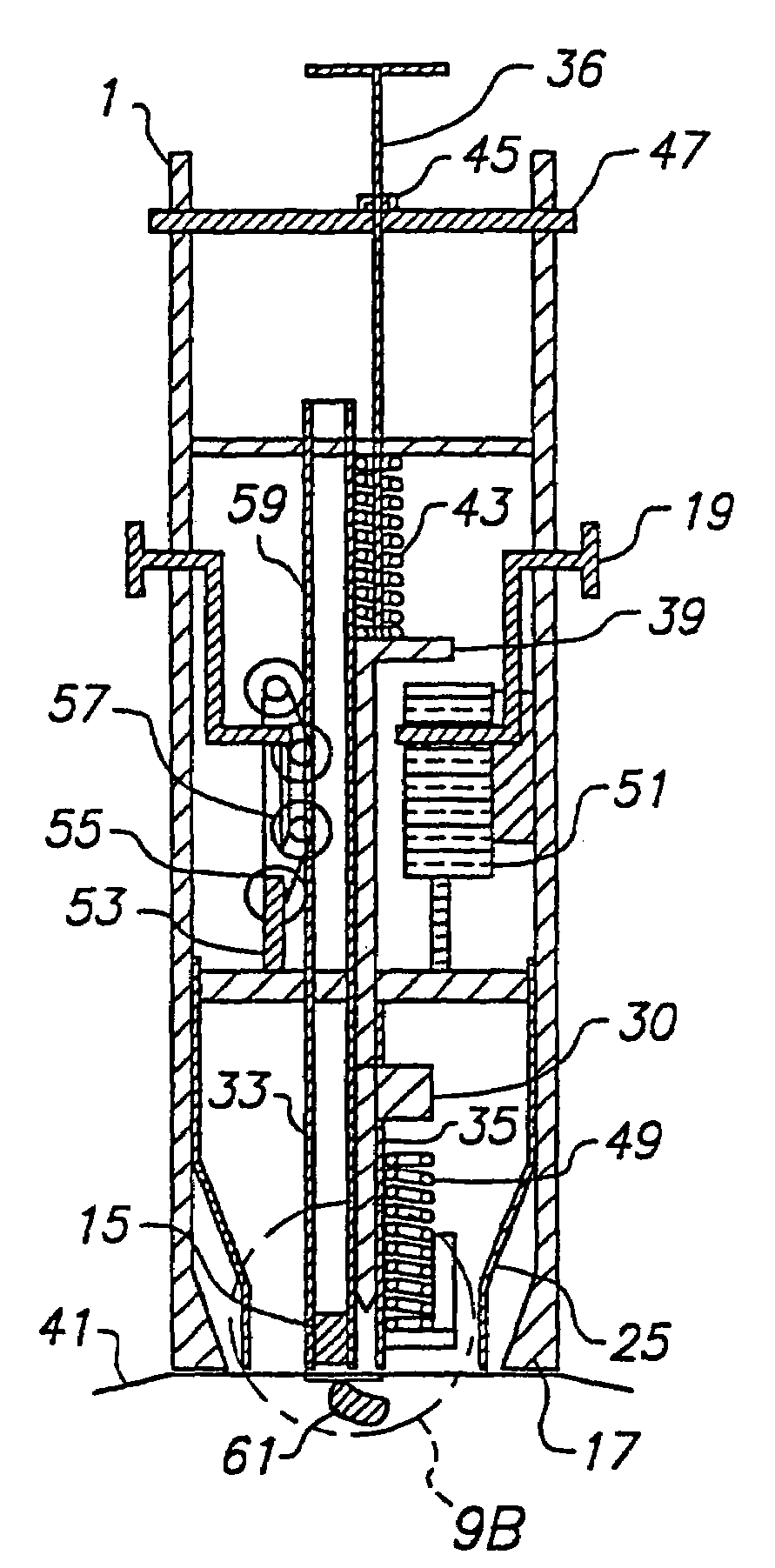
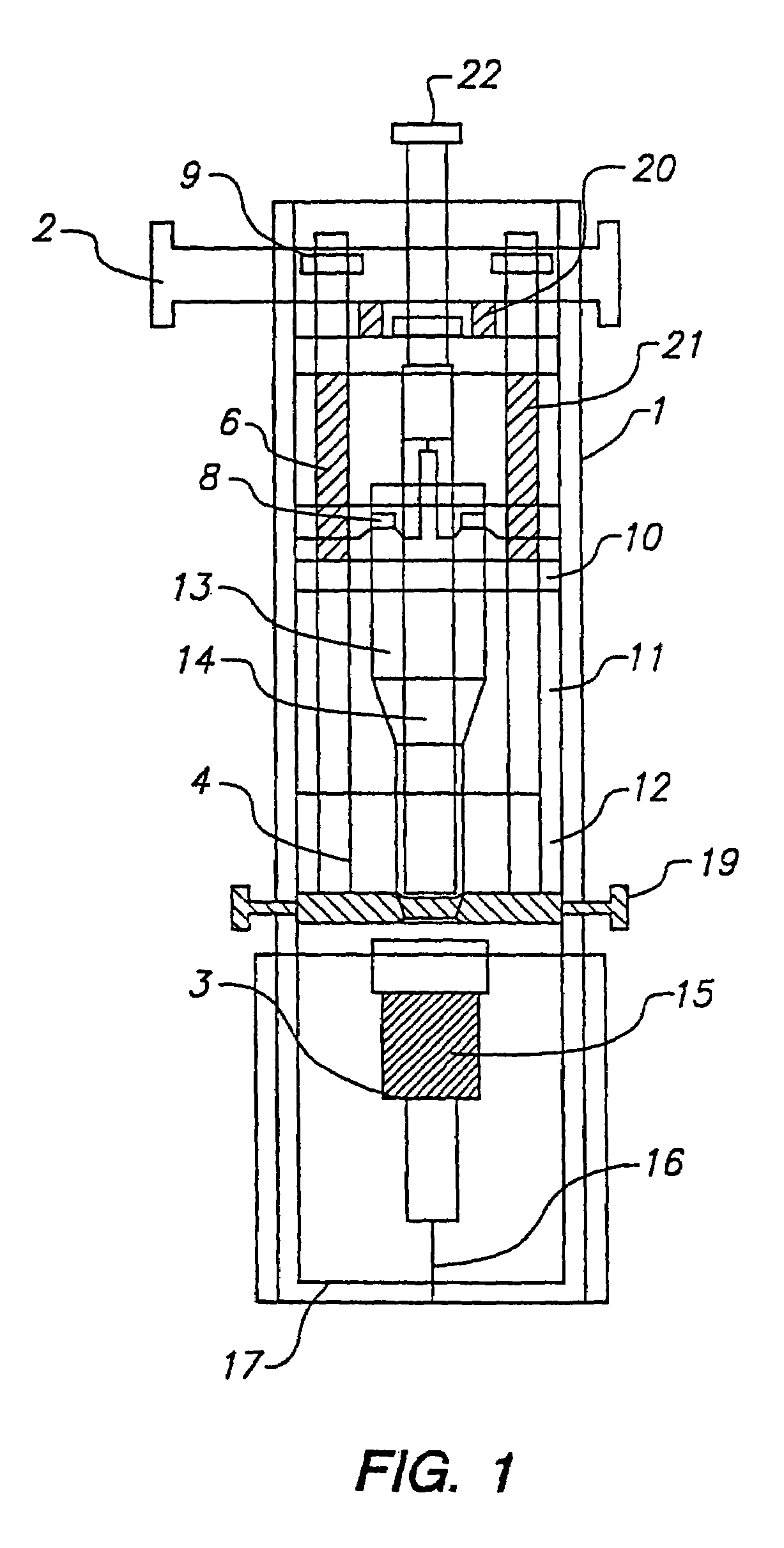
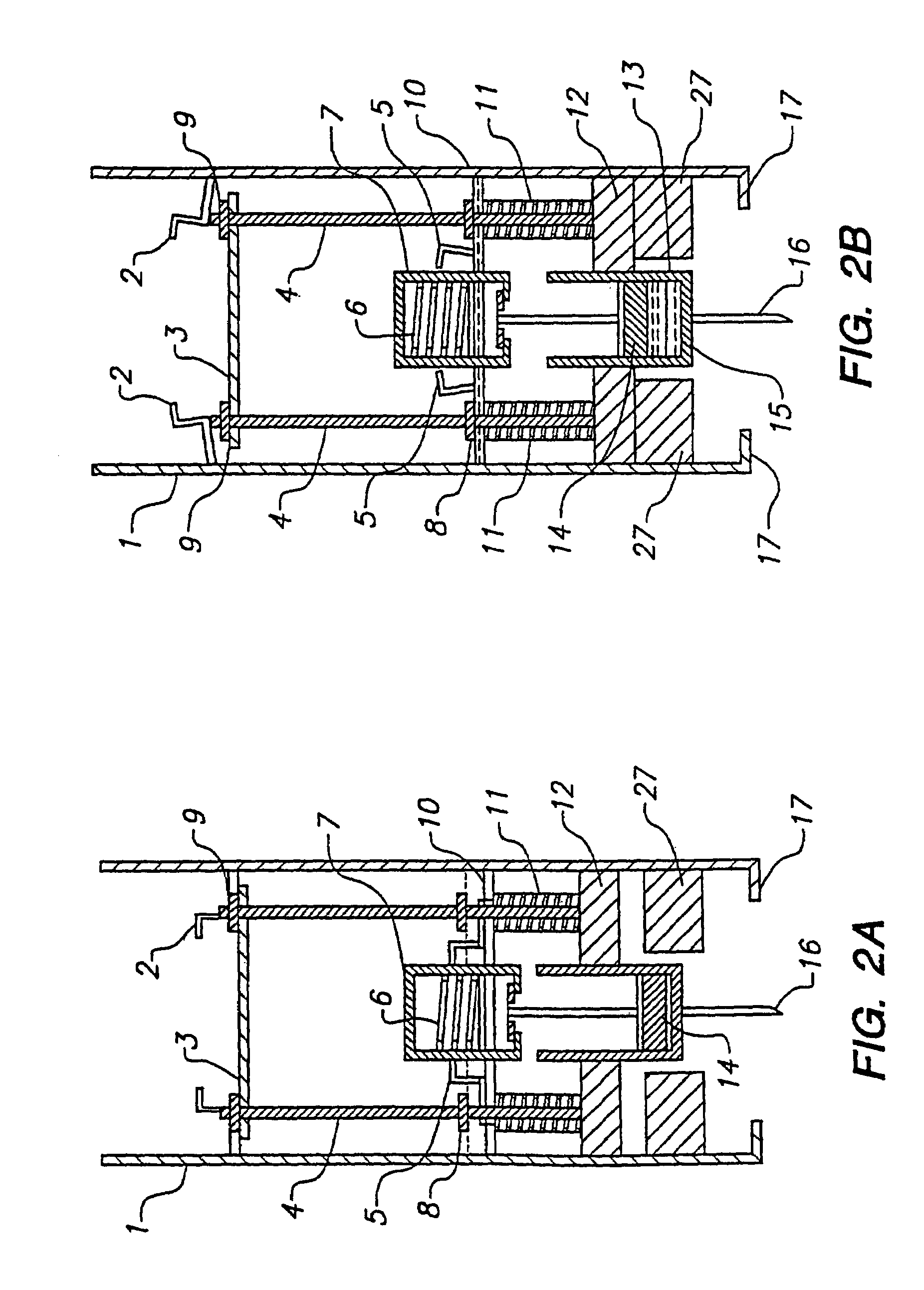
[0079]FIG. 1 illustrates a minimally invasive sampling device according to the invention. The device is comprised of numerous components which will be more fully described below. The main body 1 supports the various mechanical components housed within the device.

[0080]The main body 1 comprises an elongated hollow cylindrical tube with openings at both ends. The sampling needle 16 which is part of the disposable 3 which is capable of being retracted or deployed so that it can protrude beyond the needle guard 17 is positioned at one end. The arming and dispensing plunger 22 protrudes from the other end. The device has a needle guard 17 which permits the loading of the disposable 3. Disposable 3 is attached to the syringe 13 and plunger 14 is released by the suction cam 8.

[0081]The syringe 13 is captivated to the drive system by syringe clamp 12 which has the main tie rods 4 anchored to it. The main drive springs 11 are captivated between the syringe clamp 12 and cross support 10 and t...


PUM


Abstract

A device and method for lancing a patient, virtually simultaneously producing and collecting a small fluid sample from a body. The device comprises a blood collection system including a lancing needle (16), drive mechanism (11), kneading or vibration mechanism (25), optional suction system (7), and sample ejection mechanism. The device is preferably sized to be hand-held in one hand and operable with one hand. The device can optionally contain integral testing or analysis component (83) for receiving the sample and providing testing or analysis indication or readout for the user. A method involves piercing the skin at a rapid rate, kneading the surrounding area by ultrasonic action, piezoelectric or mechanical oscillation to stimulate the blood flow from the wound, drawing the fluid using a pumping system.

Description

[0001]This application is a continuation of application Ser. No. 09 / 988,799, filed Nov. 20, 2001, which is a continuation of application Ser. No. 09 / 180,839, filed May 10, 1999, now U.S. Pat. No. 6,332,871, which was the National Stage of International Application No. PCT / US97 / 08762, filed May 16, 1997, which claims the benefit of U.S. Provisional Application No. 60 / 017,133, filed May 17, 1996, the entirety of which are hereby incorporated by reference.FIELD OF THE INVENTION[0002]The present invention relates to devices and methods for obtaining samples of blood and other fluids from the body for analysis or processing.BACKGROUND OF THE INVENTION[0003]Many medical procedures in use today require a relatively small sample of blood, in the range of 5-50 μL. It is more cost effective and less traumatic to the patient to obtain such a sample by lancing or piercing the skin at a selected location, such as the finger, to enable the collection of 1 or 2 drops of blood, than by using a phle...

Claims


Application Information

Patent Timeline
Patent Type & Authority Patents(United States)
IPC IPC(8): A61B5/00A61B5/15A61B10/00A61B17/00
CPCA61B5/1411A61B5/14532A61B10/0045A61B2010/008A61B2017/00765A61B2562/0295A61B5/150022A61B5/150083A61B5/15019A61B5/150198A61B5/150358A61B5/150396A61B5/150503A61B5/150984A61B5/15113A61B5/15117A61B5/15136A61B5/1519A61B5/15194A61B5/157
Inventor DOUGLAS, JOEL S.ROE, JEFFREY N.RADWANSKI, RYSZARDGRAGE, HENRY M.SANCHEZ, MICHAEL S.
Owner ROCHE DIAGNOSTICS OPERATIONS INC
Why Eureka
Try Eureka