Information processing method and apparatus

a technology of information processing and equipment, applied in the field of information processing methods and equipment, can solve the problems of insufficient capture of image characteristic of a marker in a shooting range, inability to accurately record, and inability to accurately place markers, etc., to achieve the effect of convenient and adequate placemen

Inactive Publication Date: 2010-03-02
CANON KK
View PDF8 Cites 15 Cited by
  • Summary
  • Abstract
  • Description
  • Claims
  • Application Information

AI Technical Summary

Benefits of technology

[0018]The present invention is directed to enable a user to easily and adequately place markers used for calculating a position.

Problems solved by technology

The problem of registration in mixed reality results in a problem of calculating a position and orientation of a shooting viewpoint in a scene (that is, in a world coordinate system).
For example, in the method described in Uchiyama et al., an error in a position and orientation of a shooting viewpoint cannot be corrected if no marker can be captured, so that registration accuracy decreases.
However, an image characteristic of a marker in a shooting range may not be adequately captured depending on a position and orientation of a shooting viewpoint.
For example, if a marker is planer, an image characteristic of the marker cannot be adequately captured when the marker is shot from a direction orthogonal to a normal of the plane.
Of course, the image characteristic of the marker cannot be captured from a position where the marker cannot be seen because it is hidden in an object.
However, if the markers are randomly placed or set in a scene, another disadvantage besides the registration accuracy occurs, for example, an increase in load of detecting markers and degradation in beauty of the scene.
However, the “guidelines generated from some findings” indicates only a desired tendency of placement of markers.

Method used


Image

  • Information processing method and apparatus
  • Information processing method and apparatus
  • Information processing method and apparatus

Examples


first embodiment

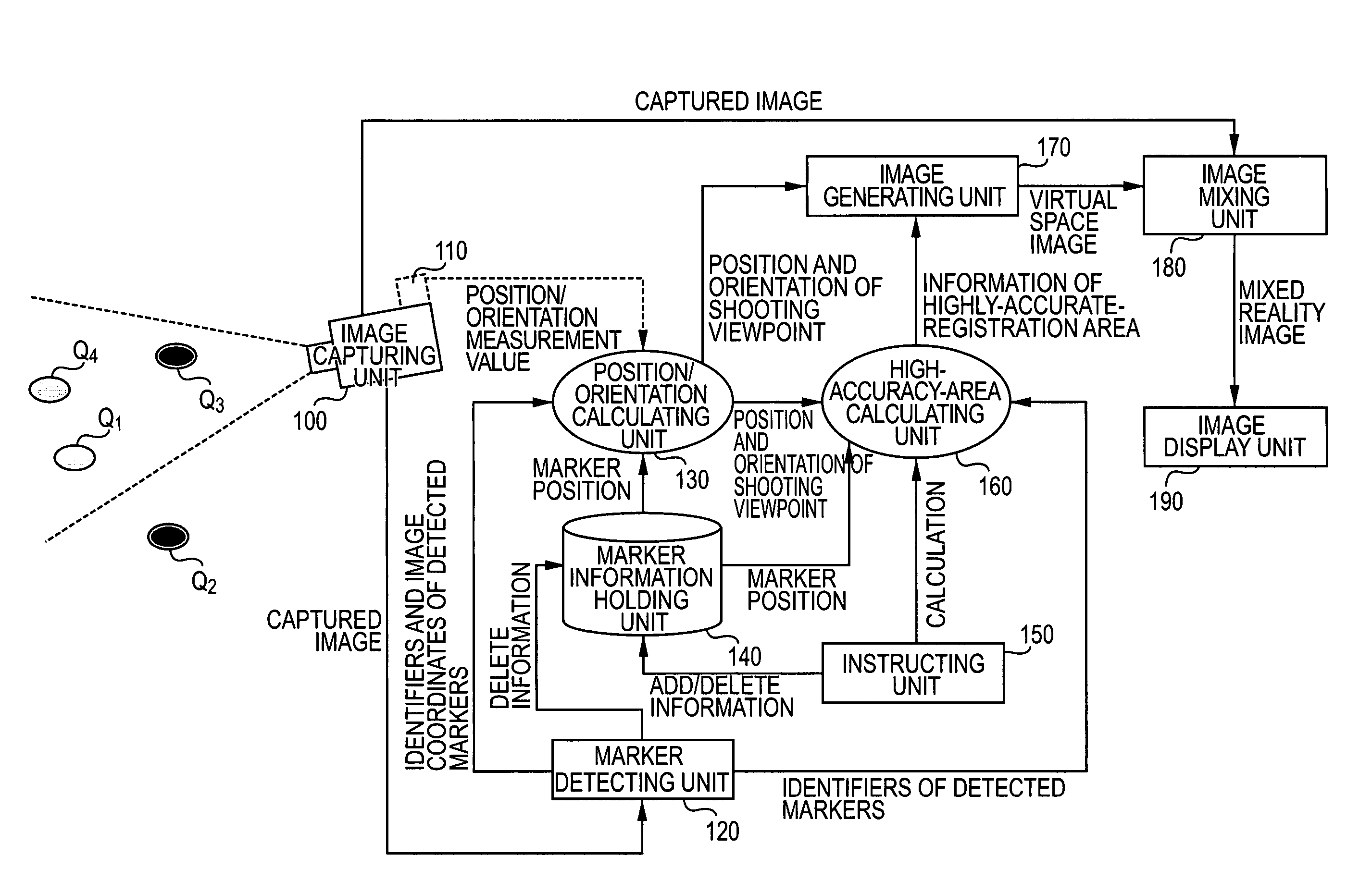
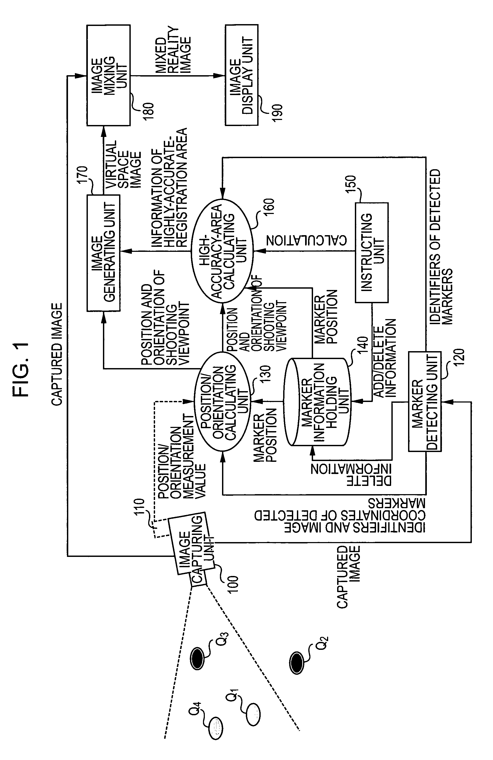
[0041]A marker placing apparatus and a marker placing method according to this embodiment visually indicate an area where highly accurate registration is likely to be or not likely to be realized by already placed markers so as to present a place to be provided with a marker to a user (who places a marker). Also, the apparatus and method present effects of deleting an already placed marker on registration accuracy to the user. Hereinafter, the marker placing apparatus according to this embodiment is described.

[0042]FIG. 1 shows an exemplary configuration of the marker placing apparatus according to this embodiment. As shown in FIG. 1, the marker placing apparatus according to this embodiment includes an image capturing unit 100; a marker detecting unit 120; a position / orientation calculating unit 130; a marker information holding unit 140; an instructing unit 150; a high-accuracy-area calculating unit 160; an image generating unit 170; an image mixing unit 180; and an image display ...

second embodiment

[0103]A marker placing apparatus and a marker placing method according to this embodiment present a position where a marker should be placed more clearly to a user by visually indicating an area where highly accurate registration is likely to be realized due to a newly placed marker before placing a marker and before placed position information is input. Hereinafter, the marker placing apparatus according to this embodiment is described.

[0104]FIG. 6 shows an exemplary configuration of the marker placing apparatus according to this embodiment. In FIG. 6, parts that are the same as those in FIG. 1 are denoted by the same reference numerals, and the corresponding description will not be repeated here. As shown in FIG. 6, the marker placing apparatus according to this embodiment includes an image capturing unit 100; a marker detecting unit 620; a position / orientation calculating unit 130; a marker information holding unit 640; an instructing unit 150; a high-accuracy-area calculating un...

third embodiment

[0155]A marker placing apparatus and a marker placing method according to a third embodiment presents an area where highly accurate registration is likely to be performed to a user in a simpler method. Hereinafter, the marker placing apparatus according to this embodiment is described.

[0156]FIG. 8 shows an exemplary configuration of the marker placing apparatus according to this embodiment. In FIG. 8, parts that are the same as those in FIG. 1 are denoted by the same reference numerals, and the corresponding description will not be repeated here. As shown in FIG. 8, the marker placing apparatus according to this embodiment includes an image capturing unit 100; a marker detecting unit 820; a position / orientation calculating unit 830; a marker information holding unit 840; an instructing unit 150; a high-accuracy-area calculating unit 860; an image generating unit 170; an image mixing unit 180; and an image display unit 190. The marker placing apparatus according to this embodiment ma...


PUM


Abstract

In a case where a position and / or orientation of a shooting viewpoint is calculated by using information about image coordinates of markers placed in a scene, the present invention enables a user to easily determine positions of the markers so that the position and orientation can be calculated more accurately. Information about markers placed in a physical space is obtained and area information about mixing accuracy between a physical space image and a virtual space image is obtained based on the information about the markers, so that a virtual space image is generated in accordance with the obtained area information.

Description

BACKGROUND OF THE INVENTION[0001]1. Field of the Invention[0002]The present invention relates to an apparatus and a method for placing (or setting: hereinafter “place” includes “set”) and / or deleting a marker in / from a scene in a case of calculating a position and orientation of a shooting viewpoint by using information about image coordinates in a captured image of markers placed in the scene.[0003]2. Description of the Related Art[0004]In recent years, studies on mixed reality have been actively conducted for the purpose of smoothly combining a physical space and a virtual space. An image display apparatus displaying mixed reality is realized by a video see-through method. In this method, an image of a virtual space (e.g., virtual objects or character information rendered by computer graphics) generated in accordance with a position and orientation of a viewpoint of an image capturing unit, such as a video camera, is mixed on an image of a physical space captured by the image capt...

Claims


Application Information

Patent Timeline
Patent Type & Authority Patents(United States)
IPC IPC(8): G09G5/00
CPCG06F3/0325G06F3/0346G06K9/3216G06T7/0042G06T7/2033G06T19/006G06K2009/3225G06T7/73G06T7/246G06V10/245
Inventor ANABUKI, MAHOROKOTAKE, DAISUKEUCHIYAMA, SHINJI
Owner CANON KK
Why Eureka
Try Eureka