
Apparatus at a spinning room machine, especially a flat card, roller card, cleaner or the like, for drawing a clothing onto a roller

a technology of clothing drawing and spinning room machine, which is applied in the direction of mechanical apparatus, engine components, textiles and paper, etc., can solve the problem that the checking procedure cannot be removed as can be necessary, and achieve the effect of simplifying the equipmen

Inactive Publication Date: 2010-03-09
TRUETZSCHLER GMBH & CO KG
View PDF13 Cites 4 Cited by
  • Summary
  • Abstract
  • Description
  • Claims
  • Application Information

AI Technical Summary

Benefits of technology

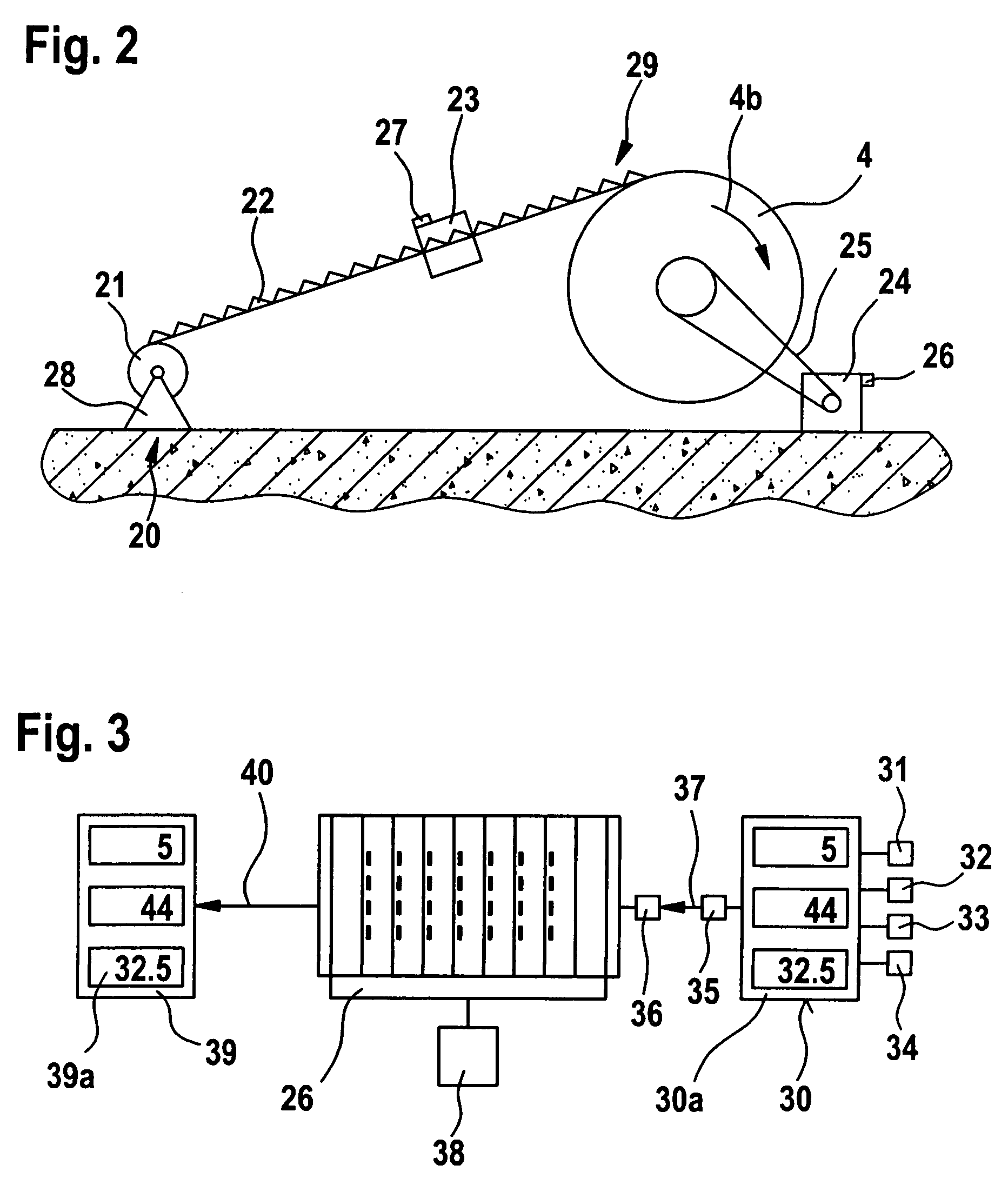
[0007]In accordance with the invention, provision can be made for the control and regulation device of the spinning room machine to be used for checking—especially by visualisation and documentation—of the current drawing-on procedure. As a result, correcting the drawing-on procedure is advantageously made possible, especially by means of the operating and display device of the spinning room machine. The ascertained data of the drawing-on procedure are available at all times where they are needed, that is to say directly at the spinning room machine, and without additional devices. When a clothing management means is installed in the control system of the carding machine, the ascertained data represent an optimum addition for the user insofar as a large number of individual drawing-on procedures are registered. The fact that the internal computer of the spinning room machine is used constitutes a very substantial simplification in terms of equipment and, in addition, advantageously allows linkage with internal data of the machine.

Problems solved by technology

A disadvantage, amongst others, in the case of that apparatus is that checking of the drawing-on procedure is not removable as can be necessary, for example, in the event of changes in loading.

Method used


Image

  • Apparatus at a spinning room machine, especially a flat card, roller card, cleaner or the like, for drawing a clothing onto a roller
  • Apparatus at a spinning room machine, especially a flat card, roller card, cleaner or the like, for drawing a clothing onto a roller
  • Apparatus at a spinning room machine, especially a flat card, roller card, cleaner or the like, for drawing a clothing onto a roller

Examples


Embodiment Construction

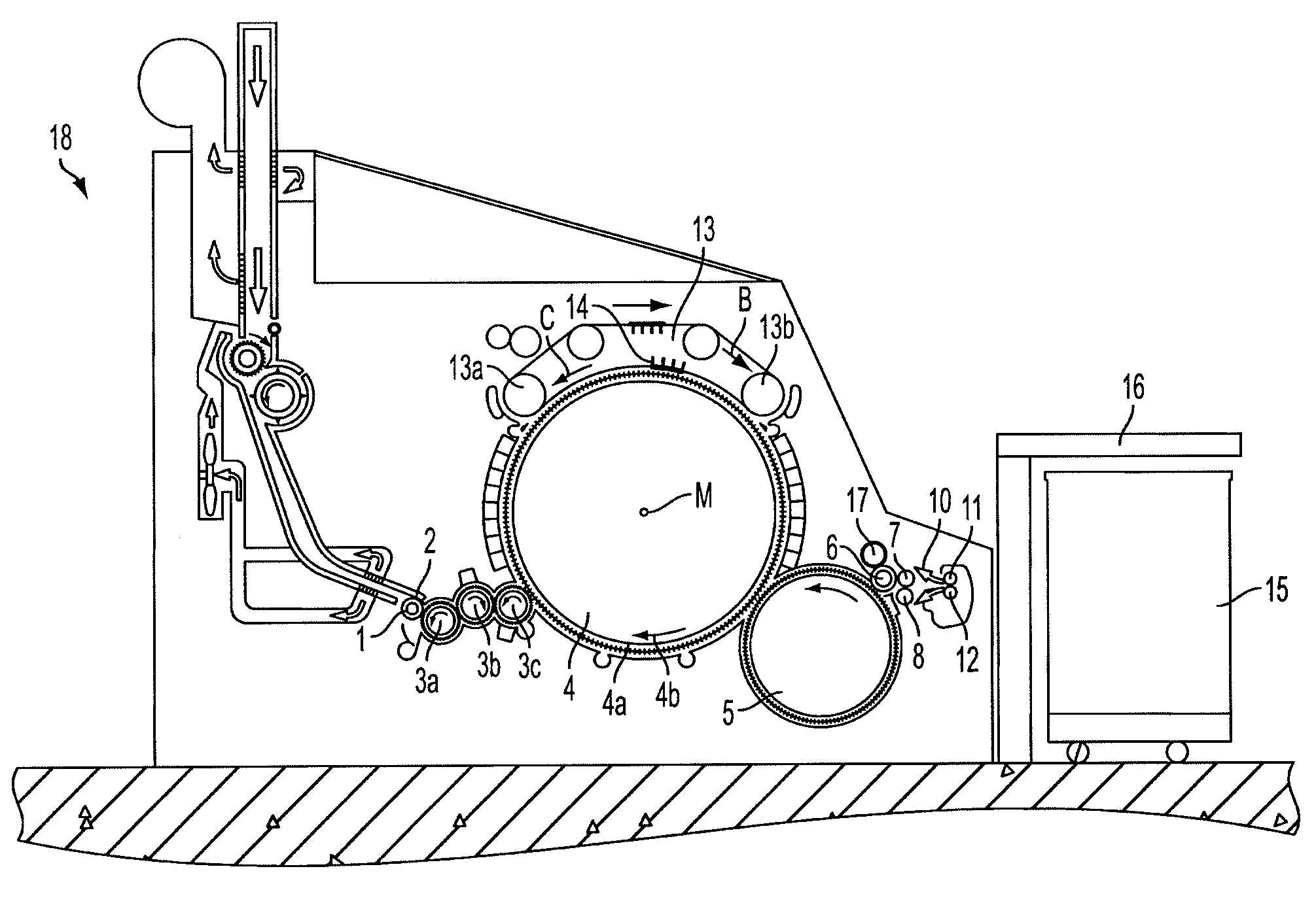
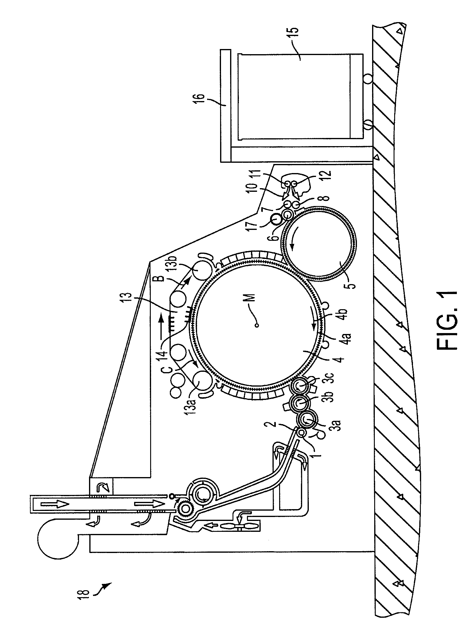
[0020]With reference to FIG. 1, a flat card, for example a TC 03 (trademark) flat card made by Trutzschler GmbH & Co. KG of Monchengladbach, Germany, has a feed roller 1, feed table 2, lickers-in 3a, 3b, 3c, cylinder 4, doffer 5, stripper roller 6, nip rollers 7, 8, web-guiding element 10, draw-off rollers 11, 12, revolving card top 13 having card-top-deflecting rollers 13a, 13b and card top bars 14, can 15 and can coiler 16. Curved arrows denote the directions of rotation of the rollers. Reference letter M denotes the centre (axis) of the cylinder 4. Reference numeral 4a denotes the clothing and reference numeral 4b denotes the direction of rotation of the cylinder 4. Reference letter C denotes the direction of rotation of the revolving card top 13 at the carding location and reference letter B denotes the direction in which the card top bars 14 are moved on the reverse side. Reference numeral 17 denotes a cleaning roller for the stripper roller 6 and reference numeral 18 denotes a...


PUM

PropertyMeasurementUnit
temperatureaaaaaaaaaa
forceaaaaaaaaaa
speedaaaaaaaaaa

Abstract

In an apparatus at a spinning room machine, especially a flat card, roller card, cleaner or the like, for drawing a clothing onto a roller using a drawing-on device, the spinning room machine has an electronic control and regulation device. In order to provide an apparatus that is simple in terms of equipment and that makes possible checking of the drawing-on procedure and / or of the measurement data, a measurement device for registering data ascertained during drawing-on is associated with the drawing-on device, and the measurement device co-operates with the electronic control and regulation device of the spinning room machine for permitting passage of data between the drawing-on device and the control and regulation device.

Description

CROSS REFERENCE TO RELATED APPLICATION[0001]This application claims priority from German Patent Application No. 10 2004 055 310.6 dated Nov. 16, 2004, the entire disclosure of which is incorporated herein by reference.BACKGROUND OF THE INVENTION[0002]The invention relates to an apparatus at a spinning room machine, especially a flat card, roller card, cleaner or the like, for drawing a clothing onto a roller.[0003]In the textile industry sector, especially in the carding sector, it is necessary for the clothings of the working apparatus, for example of a cylinder, to be replaced from time to time. The clothings are parts that are subject to wear.[0004]In a known apparatus (DD 240 569 A1), there is provided a drive system for flat cards or roller cards having at least one speed-controlled three-phase current motor, with which there is associated a speed control device. The speed of rotation of each three-phase current motor can be controlled using a frequency converter, which can in ...

Claims


Application Information

Patent Timeline
Patent Type & Authority Patents(United States)
IPC IPC(8): D01G15/84D01G15/92
CPCD01G15/92Y10T29/53526Y10T29/5353Y10T29/49545
Inventor HOSEL, FRITZ
Owner TRUETZSCHLER GMBH & CO KG
Learn More