
Parallel manipulator

a manipulator and parallel technology, applied in the field of robotic manipulators, can solve the problems of increasing the manufacturing cost of the whole unit, and increasing the complexity of the control system

Inactive Publication Date: 2010-03-09
POLYVALOR S E C
View PDF9 Cites 16 Cited by
  • Summary
  • Abstract
  • Description
  • Claims
  • Application Information

AI Technical Summary

Benefits of technology

[0019]Therefore, in accordance with the present application, there is provided a manipulator for supporting and displacing an object, comprising: a base; a moving portion adapted to support the object; at least two articulated mechanisms each having at least five rotational joints between links, with each articulated mechanism being connected to the base by two of said rotational joints, the moving portion being connected to both said articulated mechanisms by moving-portion joints, the articulated mechanisms and moving-portion joints being arranged with respect to each other between the base and the moving portion so as to constrain movement of the moving portion to displacements in two translational degrees of freedom and two rotational degrees of freedom with respect to the base; and at least four actuators being each operatively connected to a different one of the rotational joints between the base and the articulated mechanisms so as to selectively control the displacements of the moving portion in any one of the four degrees of freedom of the moving portion.
[0020]Further in accordance with the present application, there is provided a manipulator for receiving and displacing an object, comprising a moving portion adapted for receiving an object; four articulated arms each comprising a proximal and a distal link connected through a revolute joint, each articulated arm connected to a base through an actuated revolute joint, first pair of supporting arms being connected through a first distal revolute joint, second pair of supporting arms being connected through a second distal revolute joint, the axes of all ten revolute joints being parallel; a moving portion comprising a first and a second member, interconnected through a joint that allows only translation of first member with respect to second member along a given direction and possibly rotation of first member with respect to second member about an axis parallel to said given direction; means for attaching said first member to one of the two distal links in said first pair of interconnected articulated arms, allowing at least two rotational degrees of freedom; means for attaching said second member to one of the two distal links in said second pair of interconnected articulated arms, allowing at least two rotational degrees of freedom.

Problems solved by technology

This manipulator is redundantly actuated, which inevitably increases the complexity of the control system and, most importantly, the manufacturing cost of the whole unit.
This manipulator uses linear actuators, which make the manipulator more cumbersome.
Furthermore, hollow spherical joints are difficult to manufacture and increase the cost of the manipulator.
In this particular device, the orientation of the pen is not controllable.
While this manipulator is theoretically attractive, it is of relatively small practical interest, since its design is cumbersome and its proper functioning relies on strict manufacturing tolerances.
Furthermore, the kinematics of such a manipulator are complex.

Method used


Image

  • Parallel manipulator
  • Parallel manipulator
  • Parallel manipulator

Examples


Embodiment Construction

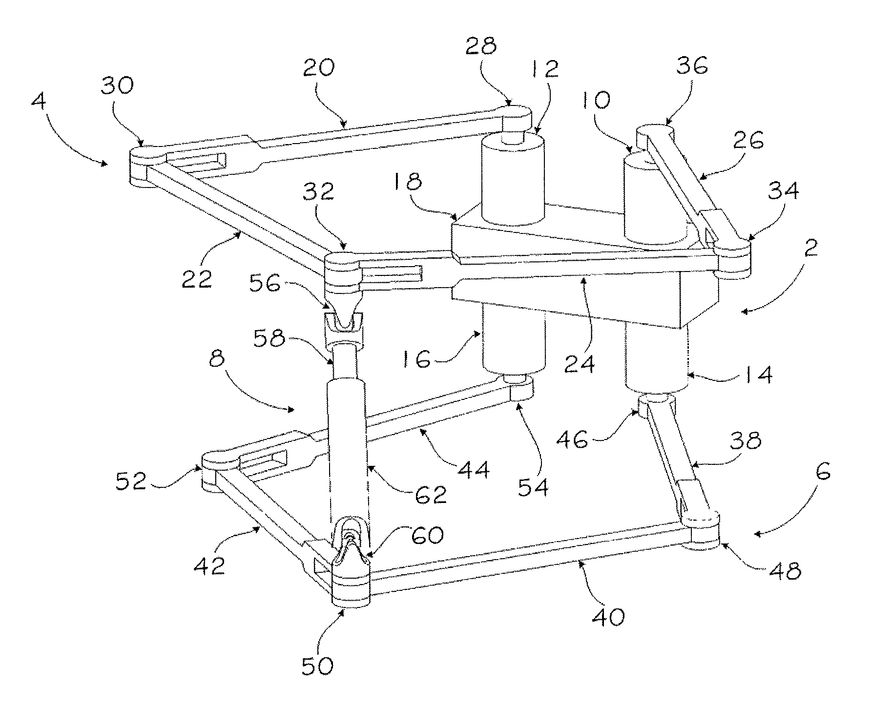
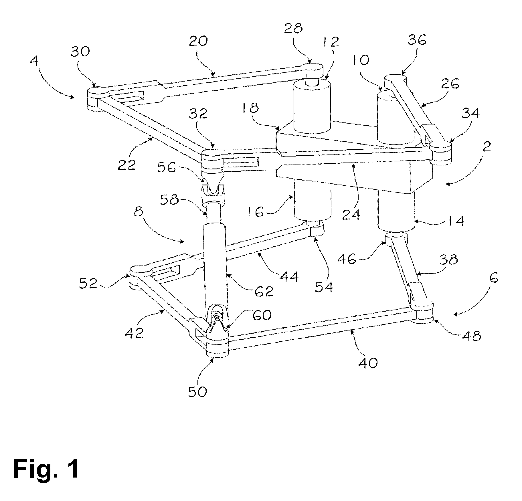
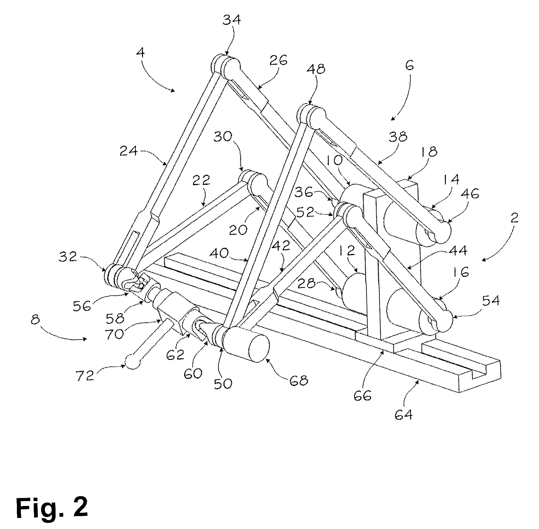
[0023]FIG. 1 shows a four-DOF (degree of freedom) parallel manipulator that can be directly used as a haptic device. The parallel manipulator has five-bar mechanisms 4 and 6, connected at one end to the base assembly 2, and arranged to support a moving portion or tool assembly 8 at the opposed end. The base assembly 2 is composed of base 18 that holds four motors, namely 10, 12, 14 and 16.

[0024]The first five-bar mechanism 4 is composed of links 20, 22, 24 and 26 and revolute joints 28, 30, 32, 34 and 36. A rotation of the links 20 and 26 is actuated by the motors 12 and 10 at the joints 28 and 36, respectively. The joints 30, 32 and 34 are passive revolute joints.

[0025]The second five-bar mechanism 6 is composed of links 38, 40, 42 and 44 and joints 46, 48, 50, 52 and 54. A rotation of the links 38 and 44 is actuated by the motors 14 and 16 at the joints 46 and 54, respectively. The joints 48, 50 and 52 are passive revolute joints.

[0026]The axes of all ten revolute joints of the tw...


PUM


Abstract

A manipulator for supporting and displacing an object comprises a base. A moving portion supports the object. Two articulated mechanisms each having five rotational joints between links, with each articulated mechanism being connected to the base by two of the rotational joints. The moving portion is connected to both the articulated mechanisms by moving-portion joints. The articulated mechanisms and moving-portion joints are arranged with respect to each other between the base and the moving portion so as to constrain movement of the moving portion to displacements in two translational degrees of freedom and two rotational degrees of freedom with respect to the base. Four actuators are each operatively connected to a different one of the rotational joints between the base and the articulated mechanisms so as to selectively control the displacements of the moving portion in any one of the four degrees of freedom of the moving portion.

Description

CROSS-REFERENCE TO RELATED APPLICATION[0001]The present patent application claims priority on U.S. Provisional Patent Application No. 60 / 941,296, filed on Jun. 1, 2007.BACKGROUND OF THE APPLICATION[0002]1. Field of the Application[0003]The present application relates to robotic manipulators and, more particularly, to such manipulators constructed to control the movement of an end-effector with at least two translational and two rotational degrees of freedom, and composed of articulated arms connecting the end-effector to a base.[0004]2. Background Art[0005]Various designs of robotic manipulators exist for controlling the movement of an end-effector with six or fewer degrees of freedom (DOFs). Among these designs, so-called parallel manipulators are becoming increasingly popular.[0006]In a parallel manipulator, an end-effector (i.e., moving portion, output portion) is connected to a base through at least two articulated arms. Often, the joint of each articulated arm that connects dir...

Claims


Application Information

Patent Timeline
Patent Type & Authority Patents(United States)
IPC IPC(8): B25J17/00
CPCB25J17/0266Y10T74/20329Y10T74/20305
Inventor LESSARD, SIMONBONEV, ILIANBIGRAS, PASCAL
Owner POLYVALOR S E C
Learn More