
Cable guard and guides for archery bows

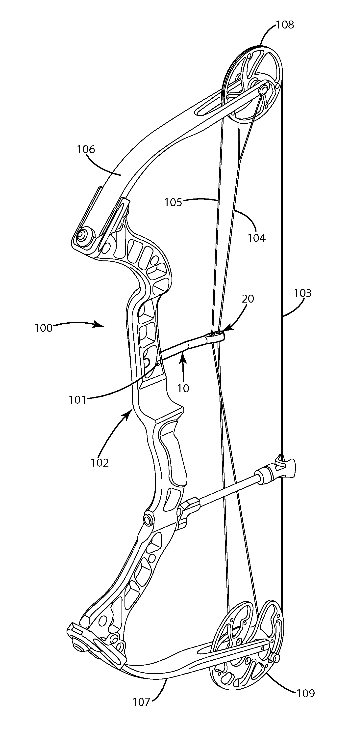
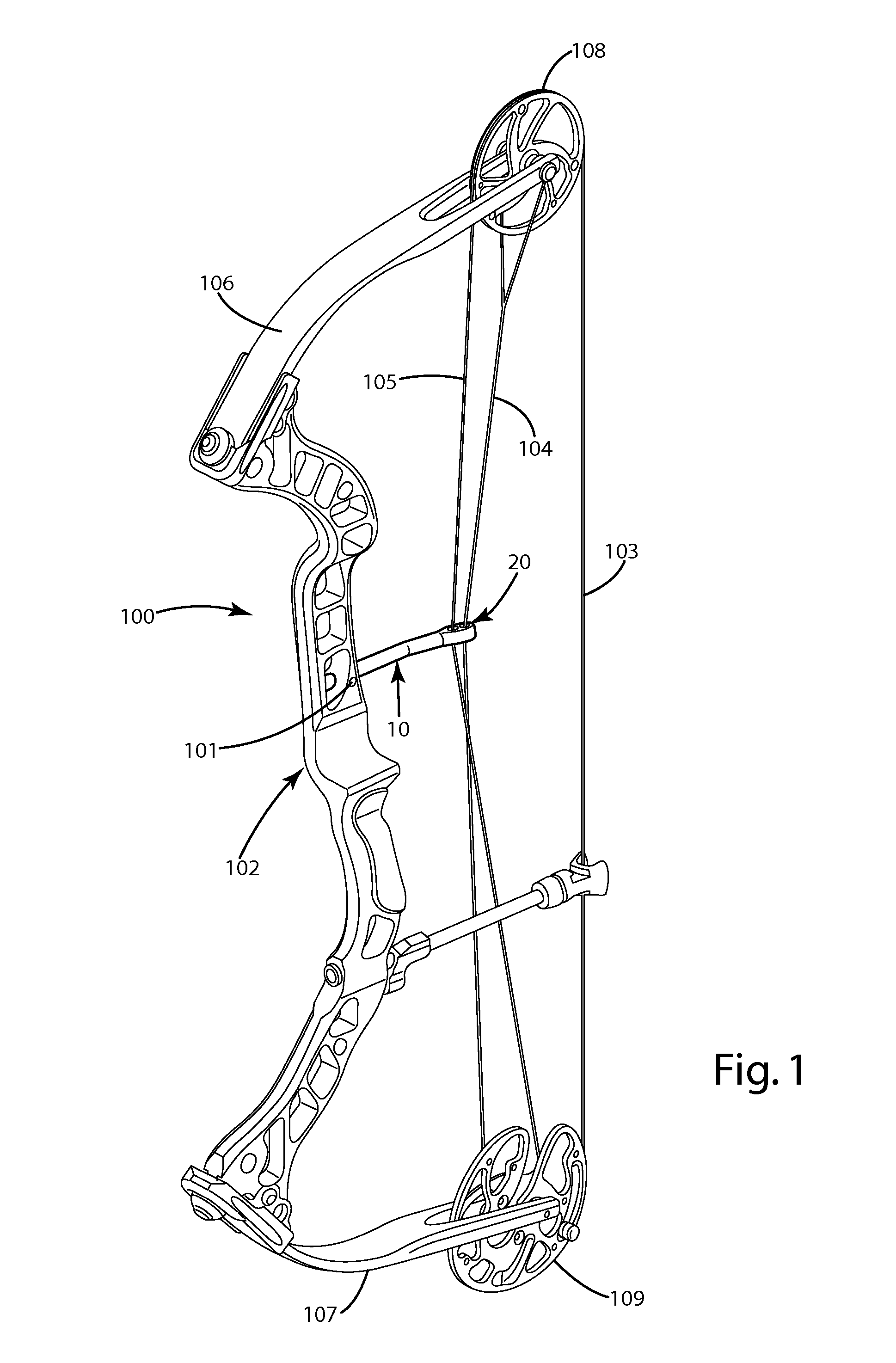
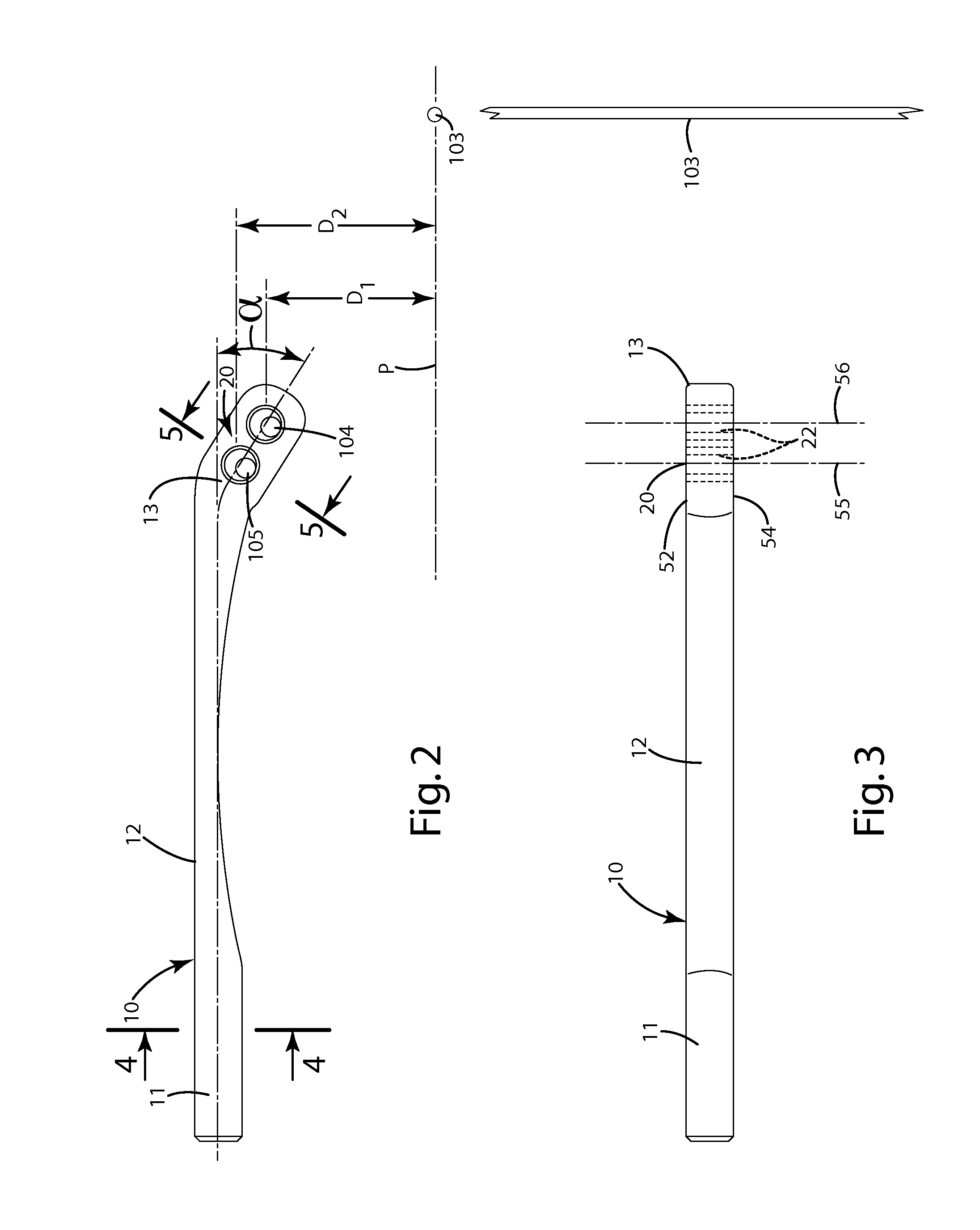
a cable guard and guide technology, applied in the field of archery bows, can solve the problems of cam leaning out of vertical alignment, cable wear, cam leaning, etc., and achieve the effect of reducing cam leaning, limb twisting, and/or cable wear

Active Publication Date: 2013-04-23
GRACE ENG
View PDF25 Cites 13 Cited by
  • Summary
  • Abstract
  • Description
  • Claims
  • Application Information

AI Technical Summary

Benefits of technology

The flexible cable guard minimizes cam lean, reduces limb twist, and decreases cable wear, enhancing shot precision and accuracy by absorbing lateral forces and reducing friction, thus improving the overall performance and longevity of the bow's components.

Problems solved by technology

For example, most conventional cable guards are rigid and relatively inflexible.
This can cause the cams to lean out of vertical alignment.
Moreover, in some cases, the limbs of the bow also may twist due to the lateral force.
Cam lean and / or limb twist can result in cable wear and possible inconsistent left-to-right shot precision and / or accuracy, which is undesirable.
Further, the sliding movement of the cable guide on the cable guard can wear both structures, generate noise, and undesirably complicate the assembly.
While this cable guard construction is designed to reduce limb twist, it is believed that its commercialization generally has been unsuccessful to date.
Moreover, because the cross section of such cable guards vary and effectively are reduced toward the end engaging the cables under force, it is believed that they might be prone to excessively deflecting or possibly breaking at that location.
Although this design provides effective cable guidance, it too includes moving parts that must be monitored for wear and surfaces that can cause premature wear or abrasion on the cables.

Method used


Image

  • Cable guard and guides for archery bows
  • Cable guard and guides for archery bows
  • Cable guard and guides for archery bows

Examples


first alternative embodiment

III. First Alternative Embodiment

[0109]FIGS. 6-8 illustrate the first alternative embodiment of the cable guard generally designated 110. This embodiment is similar to the above embodiment in structure and operation with a few exceptions. For example, the riser end 111 is circular in cross section and is provided with a flattened section or notch 114. A set screw 101, threaded in the riser 102, engages the notch 114 to retain the cable guard 110 in a fixed, generally immovable configuration relative to the riser. Other mechanisms can be used to secure the cable guard 110 to the bow 100. For example, the cable guard 110 can be threaded on its riser end 111 which can engage a corresponding threaded hole in the riser 102. Other optional fasteners, such as clamping devices, can be included on the riser, and can hold the cable guard 110 fixedly joined with the riser 102.

second alternative embodiment

IV. Second Alternative Embodiment

[0110]FIGS. 9-11 illustrate the second alternative embodiment of the cable guard generally designated 210. This embodiment is similar to the above embodiments in structure and operation with a few exceptions. For example, the riser end 211 is rectangular in cross section and is provided with two through, or optionally threaded, holes 214A and 214b for the purpose of mounting and securing the guard 210 to the side of the riser 102. Depending on the configuration of the holes in the two members, the guard 210 may be mounted to the riser 102 using either screws or bolts. Optionally, the guard 210 may be secured by other fasteners such as bolts positioned in corresponding through holes in the riser 102 and the front portion 211 of the guard 210. Optionally, screws or similar devices may be used, positioned in through holes in either the riser 102 or the front portion 211 of the guard 210 and engaging threaded holes in the opposite member.

third alternative embodiment

V. Third Alternative Embodiment

[0111]A third alternative embodiment of the cable guard is shown in FIG. 12 and generally designated 310. This embodiment is similar to the above embodiments in structure and operation with a few exceptions. For example, this cable guard 310 is joined with a mounting bracket 340. The mounting bracket 340 includes a boss 341 adapted to be inserted into a bore of the bow riser 102. Optionally, the boss 341 can be held in the bore of the riser 102 by a set screw as described above, or other fasteners. The mounting bracket also can include an offset portion 342 that extends away from the boss 341. This offset portion 342 can define a bore 343 and, optionally, a threaded hole that accepts a set screw 350 for retaining the cable guard 310 in the mounting bracket 340. The axis of this bore 343 can be offset from the axis of the boss 341. The bore 343 can be sized to provide a slip fit for the riser end 311 of the cable guard 310.

[0112]Movement in the directio...


PUM


Abstract

An archery bow is provided including a cable guard and / or cable guide that can flex to selectively move a cable relative to a plane in which a bowstring of the bow travels to minimize cam lean, limb twist, and / or cable wear. The cable guard and / or guide can move toward the bowstring plane as the bowstring is drawn, and away from the bowstring plane, out of the way of the bowstring and any attached arrow, after the bowstring is released. The cable guard can define a bore, for example, an elongated bore, extending through it along an axis that is generally parallel to the bowstring when the bowstring is undrawn. The cable guard bore can operate as a cable guide, and can include a rounded opening to minimize abrasion to a cable moving through it. A ceramic element can be included in the bore to minimize abrasion to the cable.

Description

BACKGROUND OF THE INVENTION[0001]The present invention relates to archery bows, and more particularly to a cable guard and cable guide for archery bows.[0002]Conventional compound archery bows include a bowstring and a set of cables, usually an up cable and a down cable, to transfer energy from the limbs and cams or pulleys (which are both referred to generally as “cams” herein) of the bow to the bowstring, and thus to an arrow shot from the bow. The cables and bowstring are strung from a cam on one limb to a cam on another limb. Typically, the bowstring is positioned very close to the cables due to the configuration of the cams. To avoid interference between the vanes of an arrow shot from the bowstring and the cables, most compound bows include cable guards.[0003]Generally, cable guards provide adequate clearance for arrow vanes or fletchings in the lateral spacing between cables and the plane in which the bowstring travels. The clearance can be achieved by offsetting the cables f...

Claims


Application Information

Patent Timeline
Patent Type & Authority Patents(United States)
IPC IPC(8): F41B5/00F41B7/00
CPCF41B5/10F41B5/14
Inventor GRACE, JR., LOUISGRACE, NATHANIEL E.
Owner GRACE ENG
Learn More