Fatigue testing of a wind turbine blade

a wind turbine blade and fatigue testing technology, applied in the field of fatigue testing of wind turbine blades, can solve the problems of fatigue failure, wind turbine blades are subjected to cyclical load during use, difficult to represent actual load during a fatigue test, etc., and achieve the effect of reducing the time taken

Active Publication Date: 2017-08-24
VESTAS WIND SYST AS
View PDF8 Cites 12 Cited by
  • Summary
  • Abstract
  • Description
  • Claims
  • Application Information

AI Technical Summary

Benefits of technology

[0034]The cyclical deflection force may be generated by the flapwise actuator at any suitable frequency. Preferably, the flapwise cyclical deflection force is generated at or substantially at a flapwise resonance frequency of the blade. As mentioned above in relation to the edgewise resonance frequency, deflecting the blade at a flapwise resonance frequency means that the force required to deflect the blade is far less than that required at other frequencies, reducing the energy requirements for the test and the required load capacity of the flapwise actuator. The flapwise resonance frequency at which the test is carried out depends on the characteristics of the blade but is generally in the region of 0.35 to 0.65 Hz, more particularly about 0.5 Hz. The edgewise cyclical deflection force and the flap

Problems solved by technology

Wind turbine blades are subjected to cyclical loading during use as a result of inertial loads and aerodynamic loads, such as lift and drag.
Such cyclical loading may cause weakening of the blades over the d

Method used


Image

  • Fatigue testing of a wind turbine blade
  • Fatigue testing of a wind turbine blade
  • Fatigue testing of a wind turbine blade

Examples


Embodiment Construction

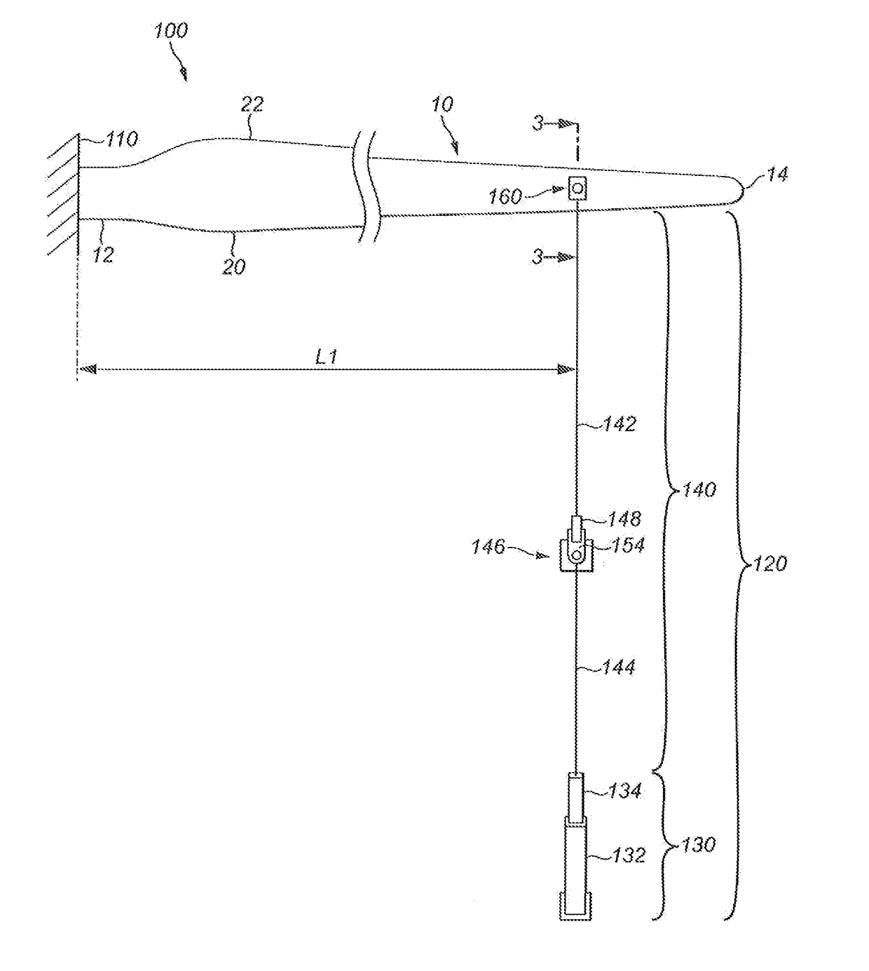
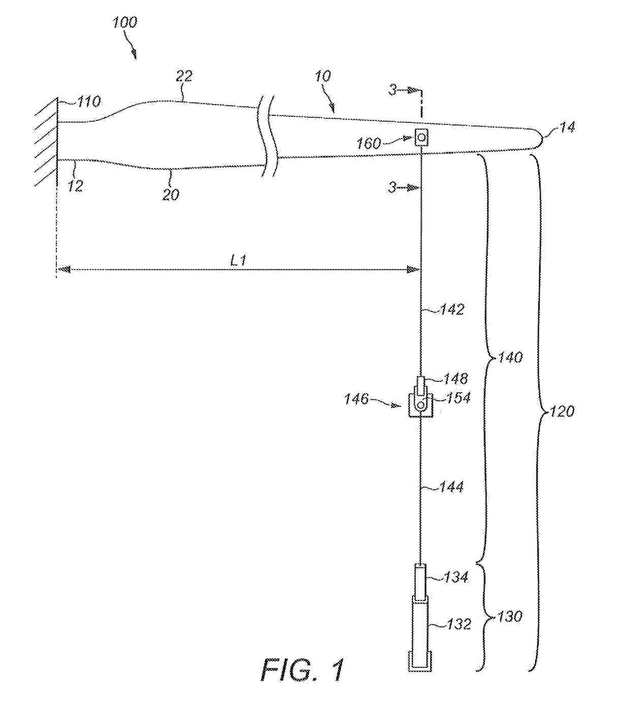
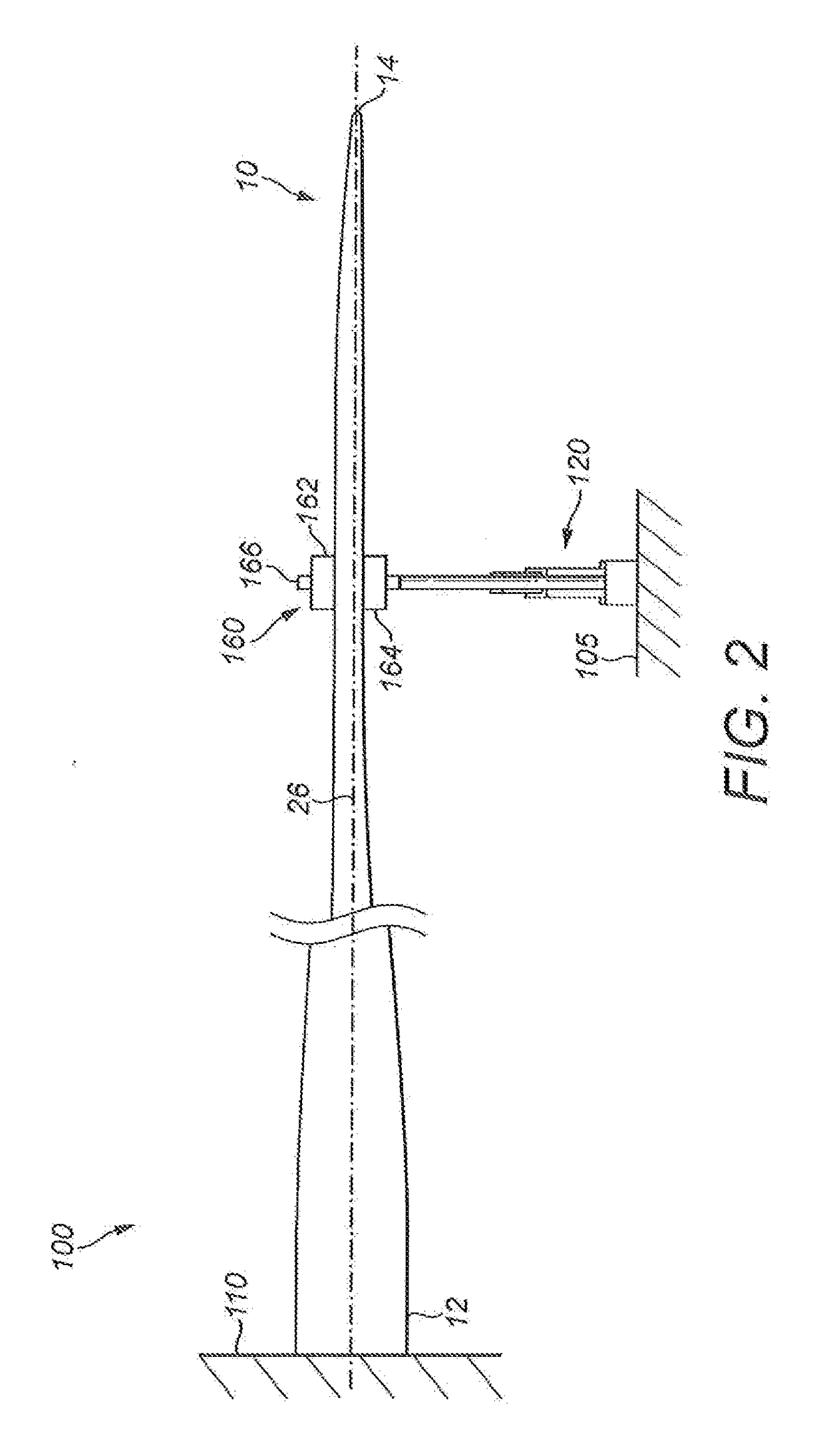
[0043]FIGS. 1 to 3 show a first test apparatus 100 for fatigue testing a wind turbine blade 10 to which the apparatus 100 is attached. The wind turbine blade 10 has a root end 12 and an opposed tip end 14. Between the root end 12 and the tip end 14 is an airfoil region having a profiled contour that comprises a pressure side 16 and a suction side 18, as well as a leading edge 20 and a trailing edge 22. An edgewise direction 24 extends between the leading and trailing edges 20, 22. The edgewise direction 24 may change along the length of the blade 10 as the shape of the blade 10 twists between the root end 12 and the tip end 14.

[0044]The test apparatus 100 comprises a base 110 and an edgewise actuator assembly 120. The base 110 comprises a fixed support structure which is mounted on a ground surface 105 of the apparatus 100, such as a steel hub that is mounted into the floor, and on which is provided a rigid mount (not shown) for fixedly supporting the root end 12 of the blade 10. As...


PUM


Abstract

The application relates to an apparatus (100) for fatigue testing a wind turbine blade, and to a system and method using such an apparatus (100). The apparatus (100) comprises a base (110) for supporting a first end (12) of the wind turbine blade (10), and an edgewise actuator assembly (120). The edgewise actuator assembly (120) includes a ground-supported edgewise actuator (130) and a flexible cable assembly (140) for connecting the edgewise actuator (130) to the blade (10). The edgewise actuator (130) and the flexible cable assembly (140) are adapted to cyclically deflect the blade (10) relative to the base in the edgewise direction by repeatedly pulling the blade (10) in a substantially horizontal direction.

Description

[0001]The present invention relates to an apparatus for fatigue testing of a wind turbine blade. In particular, the present invention relates to an apparatus for fatigue testing of a wind turbine blade comprising a base for supporting a first end of the wind turbine blade and an edgewise actuator assembly for cyclically deflecting the blade relative to the base in the edgewise direction. The present invention also relates to a method of fatigue testing a wind turbine blade.[0002]Wind turbine blades are subjected to cyclical loading during use as a result of inertial loads and aerodynamic loads, such as lift and drag. These loads are experienced in both the edgewise and flapwise directions of the blade. The edgewise direction is perpendicular to the longitudinal axis of the blade and generally parallel to a plane extending through the leading and trailing edges of the blade and corresponds to the direction of rotation of the blade during use. The flapwise direction is perpendicular b...

Claims


Application Information

Patent Timeline
IPC IPC(8): G01M5/00G01M7/06
CPCG01M5/0075G01M7/06G01M5/0066G01M5/0016
Inventor RICHARDS, WILLIAM DAVIDGUY, STUARTBARNSLEY, MALCOLM
Owner VESTAS WIND SYST AS
Why Eureka
Try Eureka