Roof truss system

a technology of roof trusses and trusses, which is applied in the direction of girders, joists, building roofs, etc., can solve the problems of large prefabricated structures, large and heavy prefabricated structures, and often not perfect uniform construction of roof trusses on the building site in residential and small commercial buildings

Active Publication Date: 2010-03-16
SYNTHEON HLDG SPA
View PDF190 Cites 40 Cited by
  • Summary
  • Abstract
  • Description
  • Claims
  • Application Information

AI Technical Summary

Problems solved by technology

The building of roof trusses on the building site in residential and in small commercial buildings is an expensive and time-consuming operation.
In addition, where a large number of such trusses need be built, they rarely turn out to be perfectly uniform.
Such prefabricated structures are large and heavy and must be shipped from the factory to the building site in small numbers on a large truck.
However, shipping height and width restrictions can impose constraints on truss geometry, particularly where the trusses are to be shipped via a public highway system.
Although piggy-back trusses solve many problems encountered when shipping the trusses to the construction site, such truss arrangements typically result in additional material handling and set up costs which increase building construction costs.
The hinge assemblies set forth in these U.S. Patents are primarily for use with wooden trusses and are not well suited for trusses formed from, for example, steel or other metal materials.
Such arrangements are generally not cost effective to transport, manufacture and install.

Method used


Image

  • Roof truss system
  • Roof truss system
  • Roof truss system

Examples


Embodiment Construction

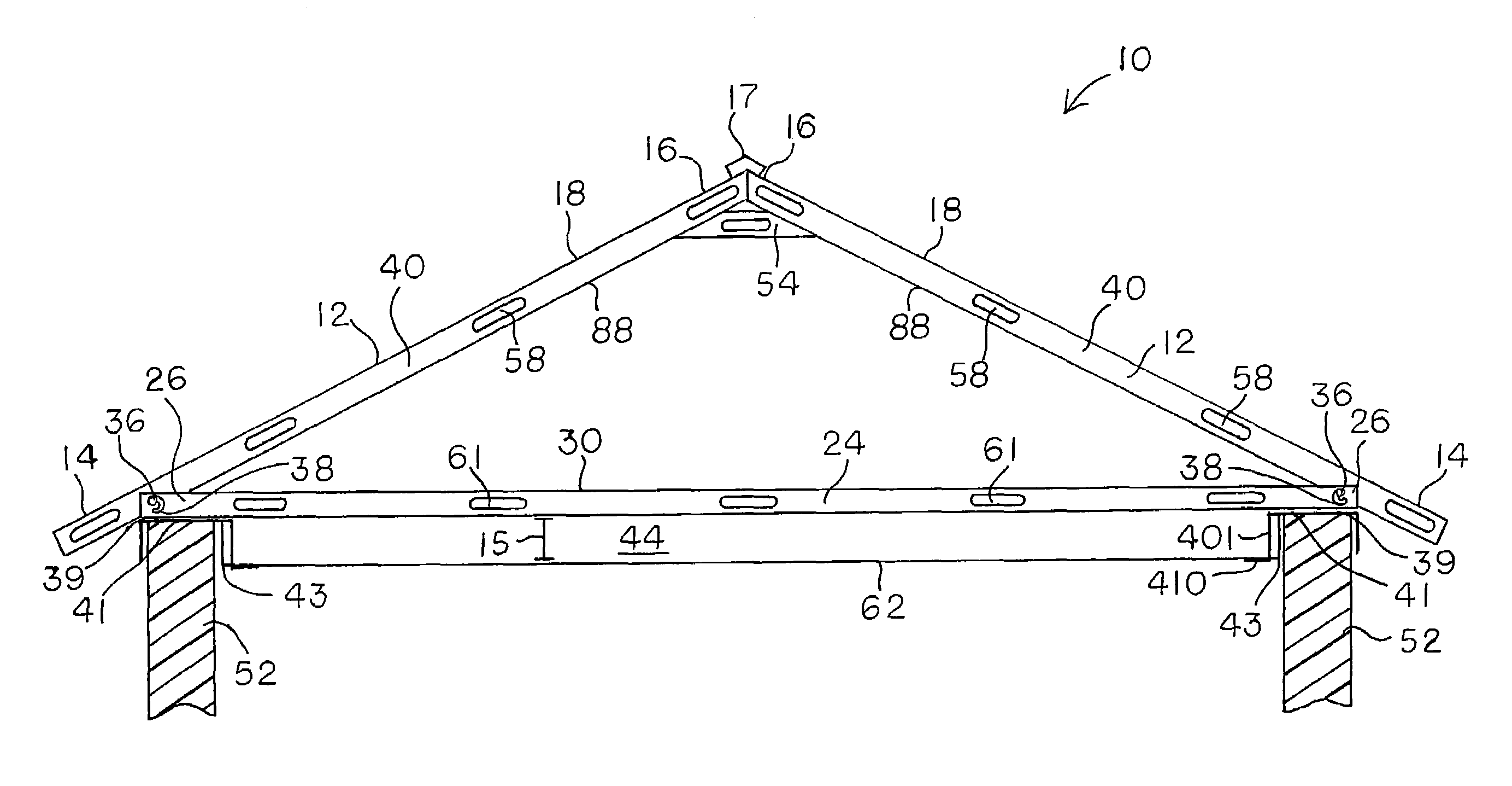
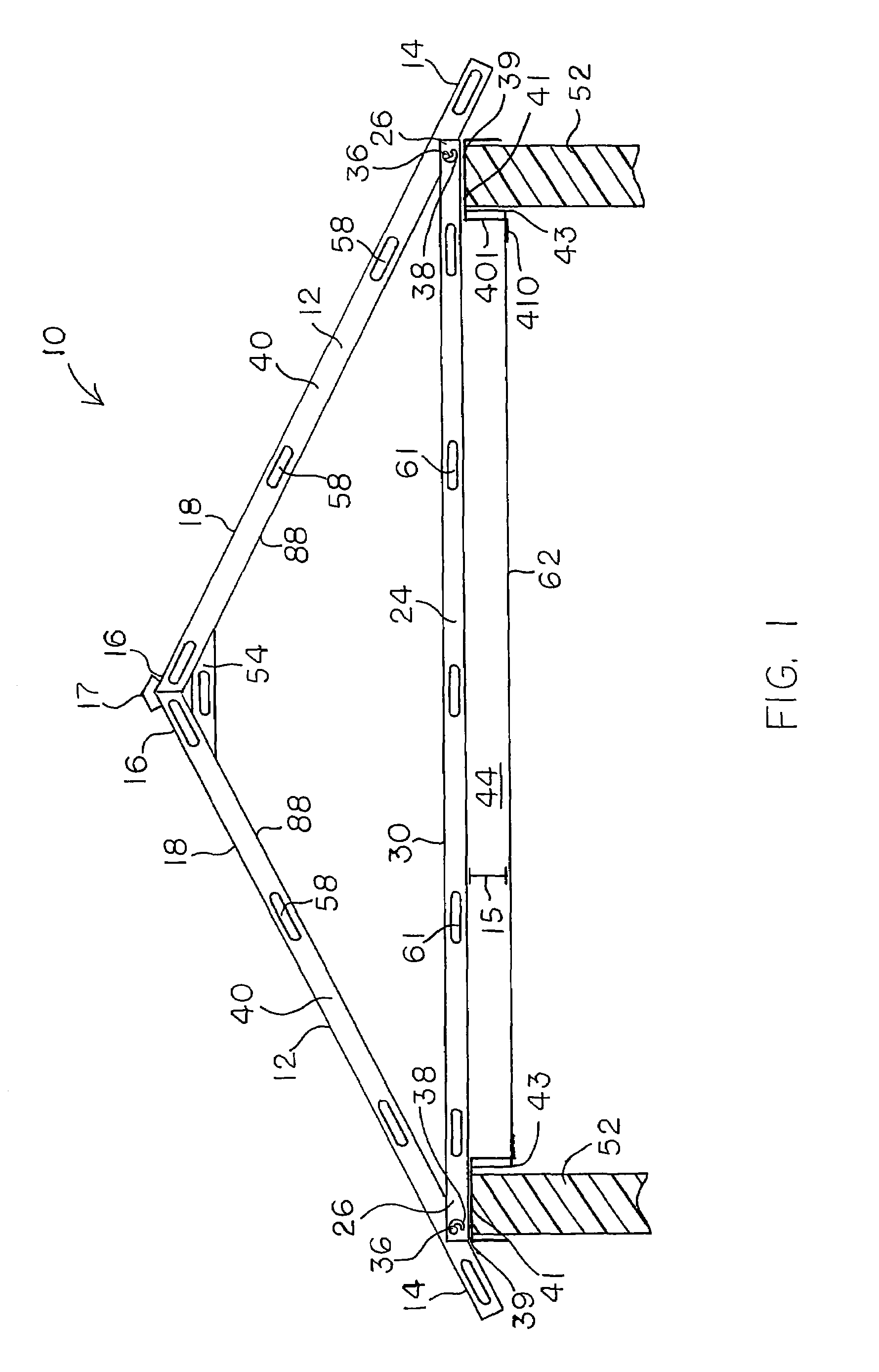
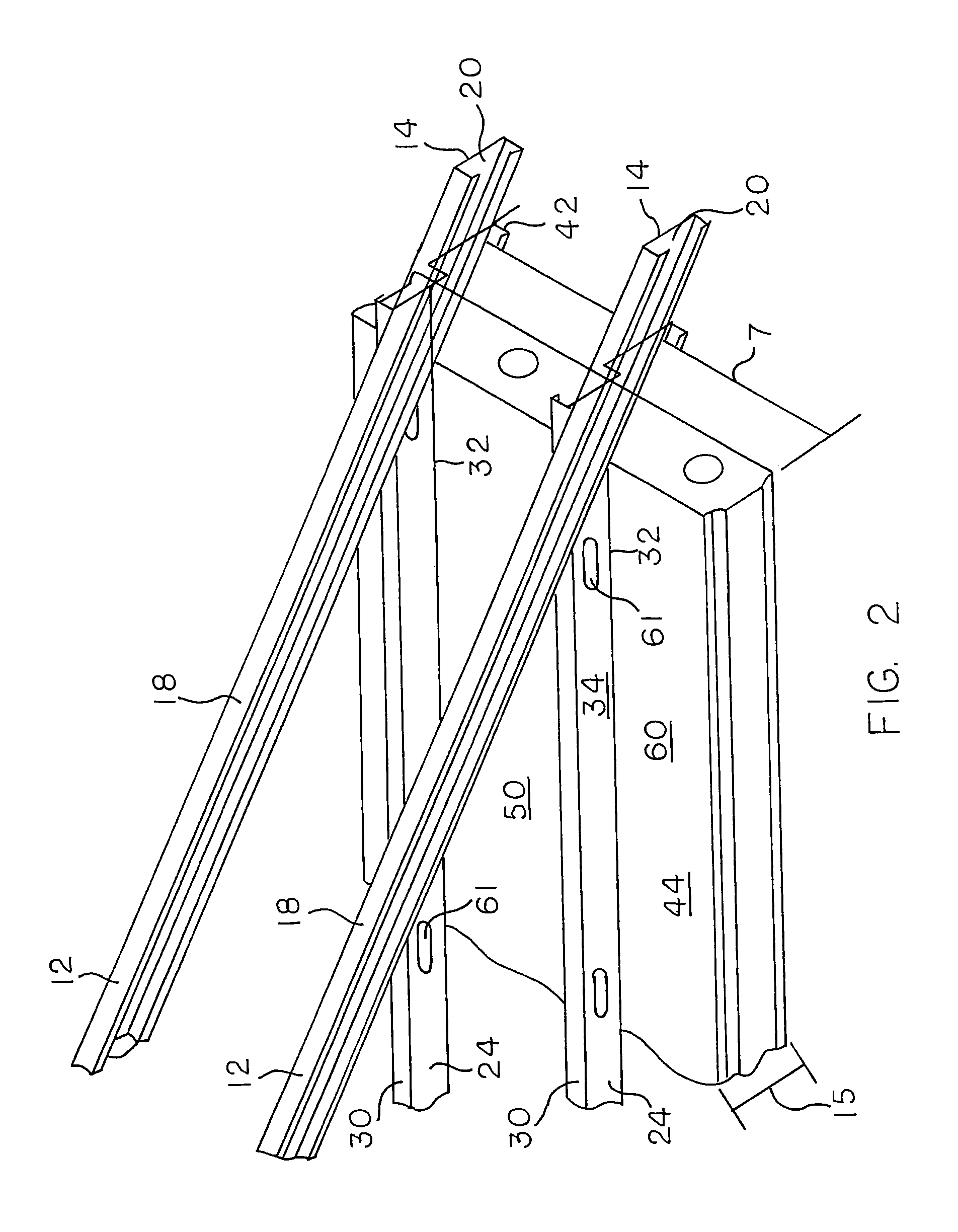
[0042]For the purpose of the description hereinafter, the terms “upper”, “lower”, “inner”, “outer”, “right”, “left”, “vertical”, “horizontal”, “top”, “bottom”, and derivatives thereof, shall relate to the invention as oriented in the drawing Figures. However, it is to be understood that the invention may assume alternate variations and step sequences except where expressly specified to the contrary. It is also to be understood that the specific devices and processes, illustrated in the attached drawings and described in the following specification, is an exemplary embodiment of the present invention. Hence, specific dimensions and other physical characteristics related to the embodiment disclosed herein are not to be considered as limiting the invention. In describing the embodiments of the present invention, reference will be made herein to the drawings in which like numerals refer to like features of the invention.

[0043]Other than in the operating examples or where otherwise indic...


PUM


Abstract

An adjustable roof truss that includes roof truss members, roof base members and a central body containing a polymer matrix. The roof truss members include a pivot end, a connection end, a roof facing edge, an inside edge, and a pivot surface. The roof base members include a receiving end, a connecting end, a top edge, a bottom edge, and a contact surface. The roof truss members are pivotally connected to the roof base members by a pivot fastener inserted through a pivot opening on the roof base members and a stator opening on the roof truss members. One or both of the roof truss members and the roof base members include an embedded portion extending from the roof facing edge or the bottom edge respectively into the central body. Expansion hole(s) are positioned along the embedded portion such that the polymer matrix expands through the expansion holes.

Description

BACKGROUND OF THE INVENTION[0001]1. Field of the Invention[0002]The present invention is directed to structural members for use in building construction and in particular to roof truss systems for construction of roof framing for supporting roofs.[0003]2. Description of the Prior Art[0004]A truss is a generally rigid frame member designed to support a structure, such as a roof or a floor. Trusses come in many shapes and sizes for a variety of applications.[0005]The building of roof trusses on the building site in residential and in small commercial buildings is an expensive and time-consuming operation. In addition, where a large number of such trusses need be built, they rarely turn out to be perfectly uniform. As a result, the building industry has gone to the prefabricated roof truss, which eliminates the costly on-site labor time.[0006]Roof trusses for commercial and residential buildings are typically prefabricated using wooden beams and metal joiner plates. Such prefabricated ...

Claims


Application Information

Patent Timeline
Patent Type & Authority Patents(United States)
IPC IPC(8): E04B1/32
CPCE04B7/022E04B7/22E04C3/09E04C3/11E04C2003/0482E04C2003/0421E04C2003/0434
Inventor BOWMAN, JAY J.
Owner SYNTHEON HLDG SPA
Why Eureka
Try Eureka