Non-contact profile measurement system

a technology of profile measurement and non-contact, applied in the field of measurement systems, can solve the problems of inability to guarantee consistent results, inability to determine anything more, and loss of production time during the time of measuremen

Inactive Publication Date: 2010-03-16
STARRETT BYTEWISE DEV
View PDF2 Cites 29 Cited by
  • Summary
  • Abstract
  • Description
  • Claims
  • Application Information

AI Technical Summary

Benefits of technology

[0012]The present invention provides a system and method for measuring features and dimensions related to the profile of a work piece. Briefly described, in architecture, the system can be implemented as follows. A sensor unit is provide that is configured to capture the profile of an object within a predetermined work zone and output data representative of said object. A control unit for receiving and processing data received from said sensor chassis is also provided.

Problems solved by technology

Again, the accuracy of this method is highly contingent upon the operator and consistent results can not be guaranteed.
These devices do not however, allow for determining anything more than cross sectional dimensions in a predetermined reference plane.
This means production time is lost during the process of obtaining a sample.
Further, since samples are taken typically at predetermined intervals, if product begins to fall out of specification between samples intervals, product output is lost before corrective action can be taken to bring the production back into spec.
This results in lost time and wasted production.
These systems do not, however, provide information about all points of interest at the same point in time.
If the product moves during measurement, then the data does not accurately represent the product.
Another drawback to this method is the initial cost and maintenance cost for such a motorized mechanism.
em. These systems suffer from inaccuracies due to non-linearity in the optics associated with the structured light sources and / or imperfections in the alignment of components that comprise the structured light sou
rce. Further, these systems do not provide the ability to inspect (evaluate) the entire profile of a work pi
The process for establishing a correlation between various the coordinate spaces associated with each sensor and a common coordinate space has been time consuming and cumbersome.
Further, these systems do not allow for the comparison of a work piece profile (as represented by captured profile data) with a predetermined reference profile, independent of the orientation of the work piece profile at the time of inspection / evaluation.
These systems also present challenges in minimizing the areas of a work piece profile that are at least partially obscured from detection by one or more of the sensors.
Thus, a heretofore unaddressed need exists in the industry to address the aforementioned deficiencies and inadequacies.

Method used


Image

  • Non-contact profile measurement system
  • Non-contact profile measurement system
  • Non-contact profile measurement system

Examples


Embodiment Construction

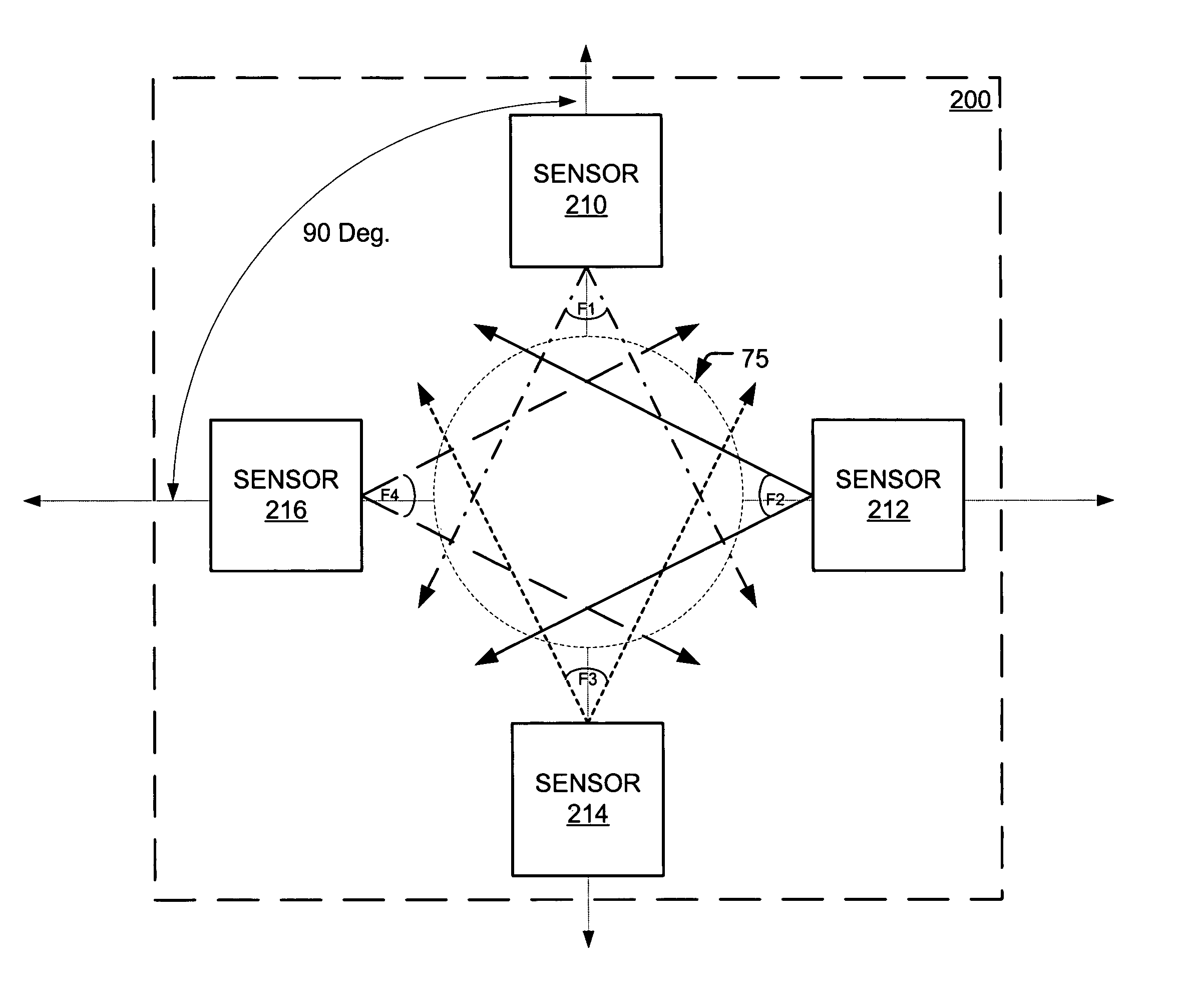
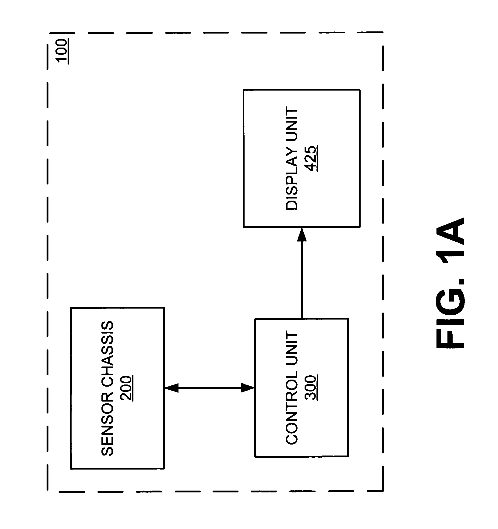
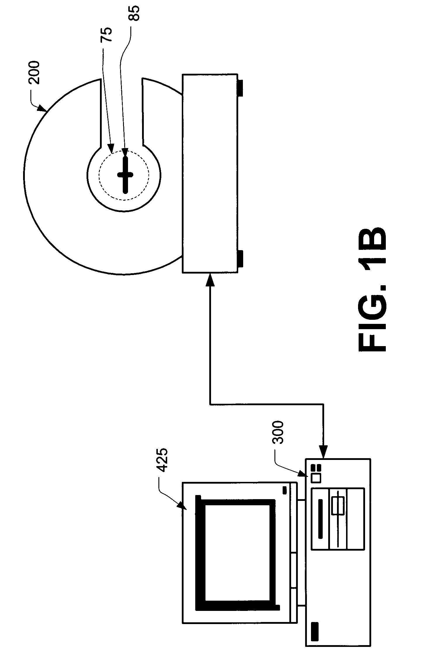
[0040]The present invention is directed to a non-contact system and method for capturing data (profile data) representing a profile of a predetermined work piece. The system is configured to provide for in-process measurement / evaluation of the work piece. In operation, the system generates a digital representation of the dimensional attributes of the profile of a work piece as it is passed along a predetermined work path. The work path will preferably be routed so that the work piece passes within a predetermined detection range.

[0041]In a preferred embodiment, the system is configured to provide for display of a visual representation of a work piece for human evaluation. The displayed representation is based upon captured profile data. Further, in a preferred embodiment, the system is configured to provide for objective evaluation of a work piece based upon a displayed visual representation. The system may include tools for determining, for example, widths, thicknesses, radii and a...


PUM


Abstract

A non contact measurement system for in-process measurement of a work piece to is described. There is provided a sensor chassis that includes one or more contour sensors for capturing the profile of a work piece and outputting coordinate values describing one or more points representative of the profile of the work piece.

Description

CLAIM OF PRIORITY[0001]This application claims priority to co-pending U.S. provisional patent application entitled, “NON-CONTACT COMPUTER CONTROL MEASUREMENT OF A WORK PIECE,” having Ser. No. 60 / 422,765, filed on Oct. 31, 2002, the disclosure of which is incorporated herein by reference, in it's entirety.TECHNICAL FIELD[0002]The present invention is generally related to measurement systems, and more particularly to a non-contact profile measurement system. The measurement system is suitable for use in, for example, continuous process manufacturing as well as other applications.BACKGROUND OF THE INVENTION[0003]In certain processes, such as manufacturing processes, it is necessary to evaluate work product in order to assure that it meets specifications or otherwise falls within predetermined criteria. For example, in extrusion processes, such as tire manufacturing, rubber material is extruded and linearly drawn into a predetermined shape for use in the tire. It is important that the s...

Claims


Application Information

Patent Timeline
Patent Type & Authority Patents(United States)
IPC IPC(8): G01B11/30
CPCG01B11/245
Inventor HARRIS, MICHAELHIDLE, ANDYBURDETTE, BEN
Owner STARRETT BYTEWISE DEV
Why Eureka
Try Eureka