Tiller operated marine steering system

a technology of marine steering and tiller, which is applied in marine propulsion, special-purpose vessels, vessel construction, etc., can solve the problems of operator fatigue, sharp curtailment of operator's freedom of movement, and change of steering angle, so as to relieve excessive hydraulic pressure and lessen seal drag condition

Active Publication Date: 2010-03-23
MARK X STEERING SYST
View PDF16 Cites 26 Cited by
  • Summary
  • Abstract
  • Description
  • Claims
  • Application Information

AI Technical Summary

Benefits of technology

[0018]In some implementations, the thermal compensator automatically regulates pressure within the hydraulic lock and also enables a user to manually relieve hydraulic pressure from the hydraulic lock to, for example, lessen a seal drag condition within the hydraulic lock, as desired. This can be done by way of a plunger assembly that a user manipulat

Problems solved by technology

These reaction forces may cause the steering angle to change unless the reaction forces are countered by the operator.
The operator's freedom of movement therefore is sharply curtailed.
The relatively large reaction forces imposed on and by larger motors require commensurately larger retention forces by the operator, leading to operator fatigue over time.
However, all of the self-locking steering systems described above are rather complex and cannot be easily installed without substantial modification

Method used


Image

  • Tiller operated marine steering system
  • Tiller operated marine steering system
  • Tiller operated marine steering system

Examples


first embodiment

2. Construction and Operation of First Embodiment

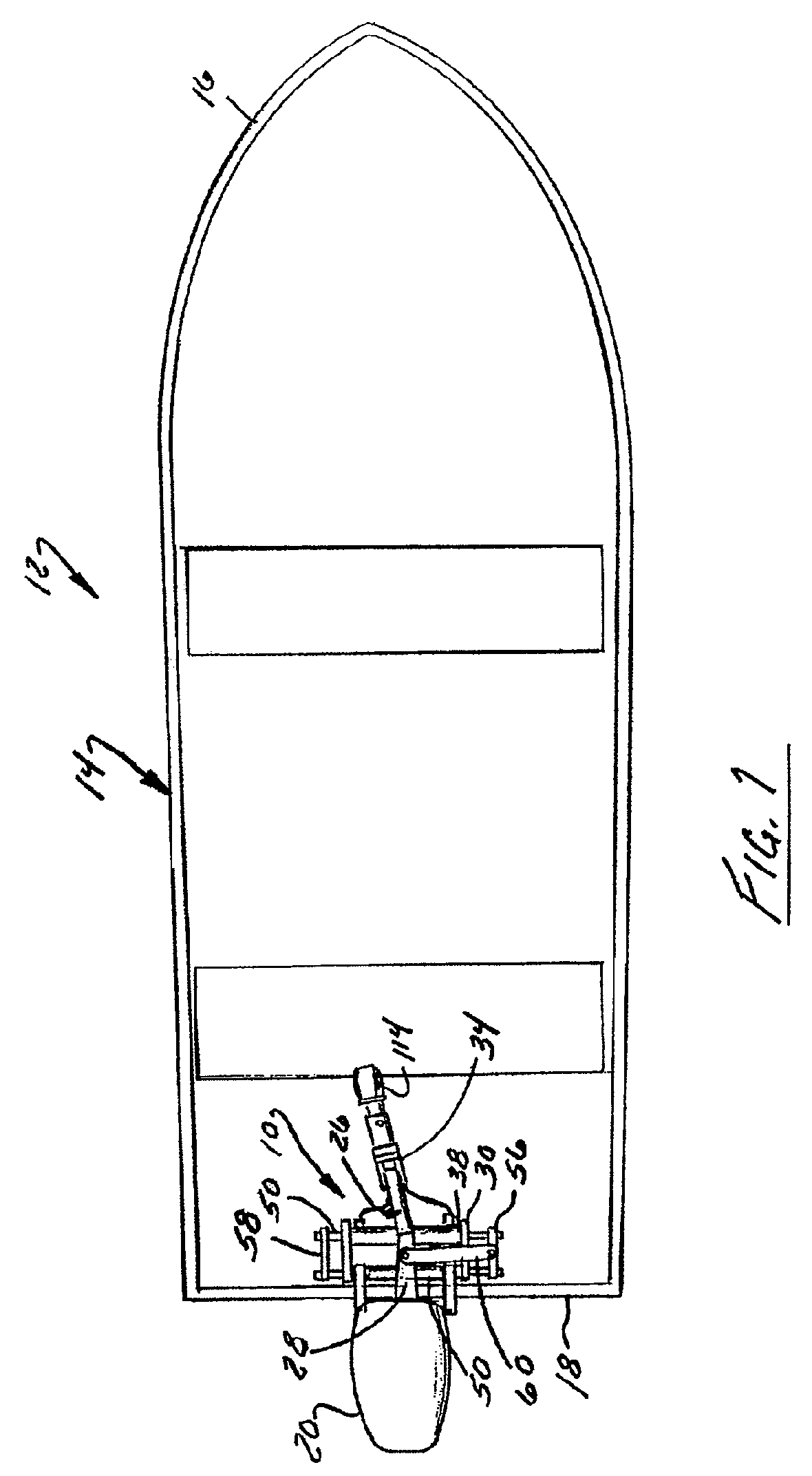
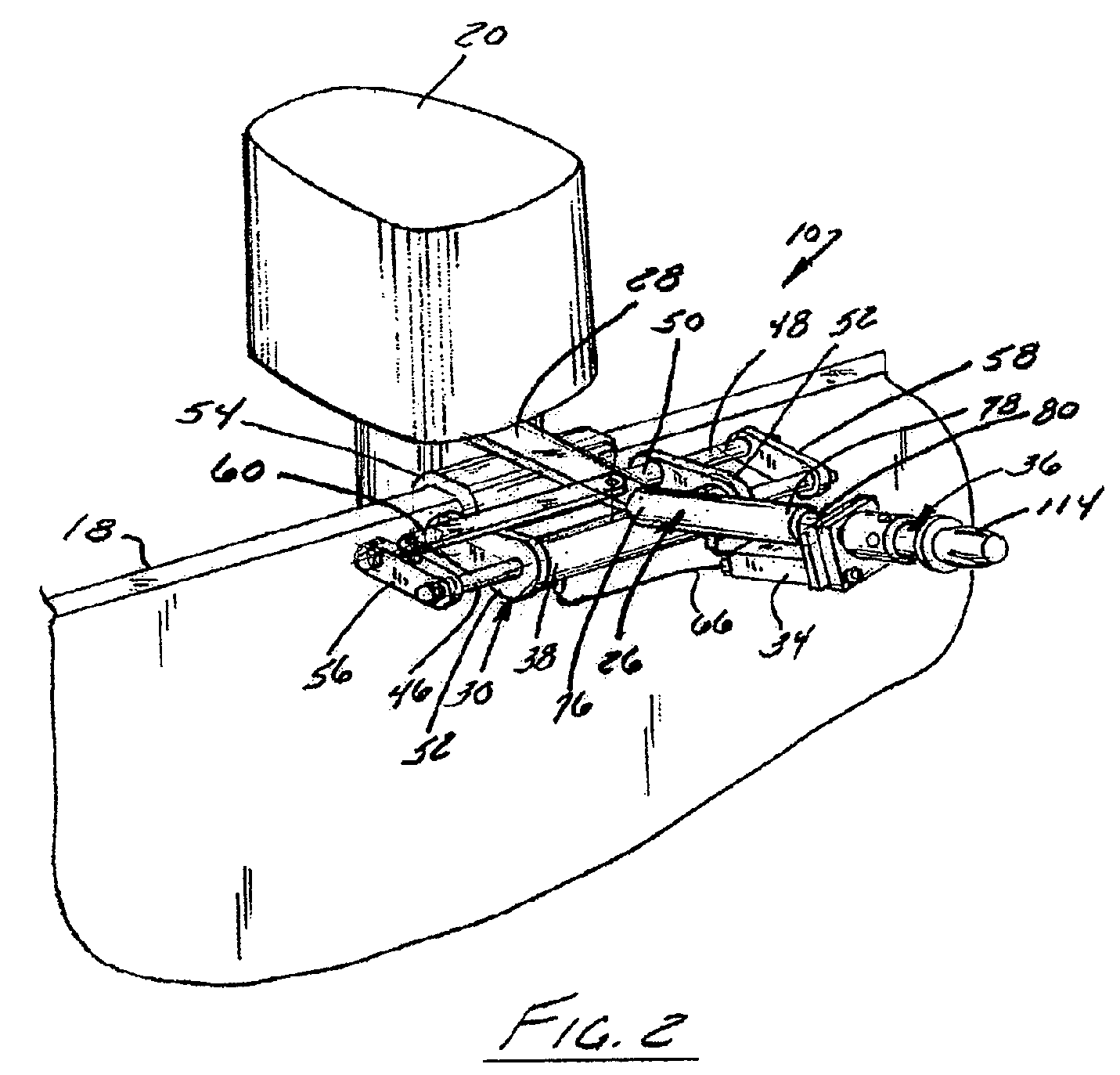
[0063]Turning now to FIGS. 2-7B and initially to FIGS. 2-4, a self-locking tiller actuated steering system 10 constructed in accordance with the first preferred embodiment of the invention include the above-described tiller, a hydraulic lock in the form of a cylinder assembly 30, and a valve assembly 32 that is housed in a valve unit 34 mounted on the underside of the tiller 26. The valve assembly 32 is responsive to tiller operation to selectively engage and disengage the hydraulic lock by selectively permitting or preventing a movable portion of the cylinder assembly 30 from moving. More specifically, the valve assembly 32 is actuated in response to movement of an actuator portion 36 of the tiller 26 relative to another portion of tiller from a neutral position thereof in order to permit fluid to flow to and from the hydraulic cylinder assembly 30 to disengage the lock and permit movement of the portion of the tiller 26 that is coup...

second embodiment

3. Construction and Operation of the Second Embodiment

[0079]Another embodiment of a self-locking steering system 210 constructed in accordance with the invention is illustrated in FIGS. 8-14. It is usable with the same boat 12 as shown in FIG. 1. It differs from the first embodiment primarily in that a more versatile valve assembly is used that is more easily incorporated into a standard tiller design and, in fact, can be retrofitted onto an existing tiller with little or no tiller modification. It is also illustrated as being used with a different cylinder assembly and steering linkage, but only for the purposes of illustrating the diversity of the invention. Components of the steering system of this embodiment corresponding to components of the first embodiment are designated by the same reference numerals in the drawings, incremented by 200. Hence, the steering system 210 includes a tiller 226, a steering arm 228, a steering cylinder assembly 230, and a valve assembly 232. The va...

third embodiment

4. Construction and Operation of Third Embodiment

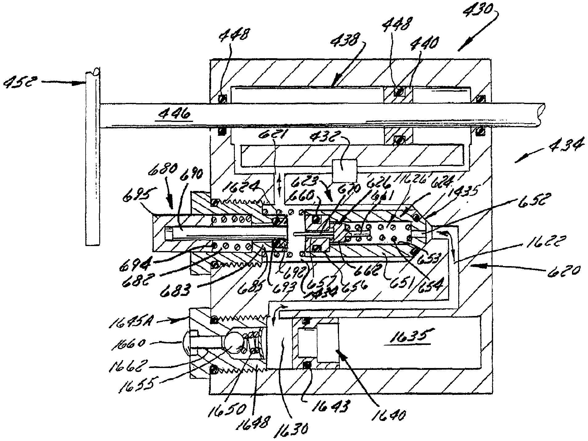
[0096]Turning now to FIGS. 16-22B, a self-locking tiller actuated steering system 410 constructed in accordance with a third preferred embodiment of the invention is illustrated. The steering system 410 differs from those of the prior embodiments in that it is considerably simpler and less expensive to manufacture and assemble. It is also potentially more reliable. The most notable difference from a functional standpoint is that the control valves are actuated remotely by cables 490 and 492 rather than directly by the actuator on the tiller, hence permitting the valve assembly to be mounted on the cylinder assembly and providing a much simpler tiller extension.

[0097]Referring initially to FIGS. 16-18, the steering system 410 of this embodiment includes a tiller 426, a hydraulic lock in the form of a hydraulic cylinder assembly 430, and a valve assembly 432 that is housed in a valve unit 434 mounted on or even formed integrally with th...


PUM


Abstract

A hydraulic lock of a tiller-based watercraft steering system is responsive to tiller release to lock a watercraft's steered element in the last commanded position upon tiller release. The hydraulic lock can be controlled through an actuator assembly that is provided between a tiller arm and the watercraft's steered element. One or more cables connect the actuator assembly to other components of the hydraulic lock. A thermal compensator regulates pressure within the hydraulic lock by accommodating changes in temperature related characteristics of the fluid within the hydraulic lock Increases in fluid pressure due to thermal expansion can be mitigated within the thermal compensator by automatically or manually directing a volume of fluid from the hydraulic lock, through a compensating valve assembly, and into a reservoir. Decreases in fluid pressure can be mitigated by directing fluid from the reservoir back into the hydraulic lock.

Description

CROSS REFERENCE TO RELATED APPLICATION[0001]This application is a continuation-in-part application of presently co-pending U.S. application Ser. No. 11 / 139,795, filed May 27, 2005, and entitled “Tiller Operated Marine Steering System,” the entirety of which is incorporated herein by reference in its entirety.BACKGROUND OF THE INVENTION[0002]1. Field of the Invention[0003]The invention relates to marine steering systems and, more particularly, relates to a steering system for a boat or other watercraft that is powered by a motor and steered by a tiller. Specifically, the invention relates to a tiller-operated steering system that is self-locking upon tiller release so as to immunize the tiller from reaction forces that would otherwise be imposed on the tiller by the motor or other steered element. The watercraft's steered element therefore retains the last steering angle commanded upon tiller release.[0004]2. Discussion of the Related Art[0005]In one type of conventional marine steer...

Claims


Application Information

Patent Timeline
IPC IPC(8): B63H25/22B63H25/00B63H25/34B63H25/10
CPCB63H20/12B63H25/00F15B13/0422
Inventor HUNDERTMARK, JAMES M.
Owner MARK X STEERING SYST
Why Eureka
Try Eureka