Latch securing member

a technology of latching member and latching plate, which is applied in the direction of coupling device connection, coupling/disconnecting parts engagement/disengagement, electrical apparatus, etc., can solve the problems of difficult removal of latching member, difficult unmating of connector housing, and difficult insertion in close working areas, etc., to facilitate the effective use of the present invention in the marketplace.

Active Publication Date: 2010-03-23
TYCO ELECTRONICS LOGISTICS AG (CH)
View PDF23 Cites 48 Cited by
  • Summary
  • Abstract
  • Description
  • Claims
  • Application Information

AI Technical Summary

Benefits of technology

[0009]The latch securing member of the present invention has numerous advantages. As the latch securing member is inserted in a direction which is essentially parallel to the longitudinal axis of the connector, the latch securing member can be used in environments in which space between components must be minimized. The latch securing member can also be used on connectors already installed in the field. As the latch securing members cooperates with known latch members, the housing of the connectors do not have to be modified to accommodate the latch securing members. Many latch securing members currently available require the connector housing to have specific openings or shoulders provided therein to accommodate the latch securing members. No such special molding of the connector housings is required for this invention. The invention also required no special tools for insertion or removal. This facilitates the effective usefulness of the present invention in the marketplace.

Problems solved by technology

However, the gauge pin member is inserted in a direction transverse to the insertion direction of the matable connector bodies, which insertion may be difficult in close working areas.
However, in this connector, once the securing member is moved into the fully secured position, it is difficult to remove the securing member, thereby making it difficult to unmate the connector housings.

Method used


Image

  • Latch securing member
  • Latch securing member
  • Latch securing member

Examples


Embodiment Construction

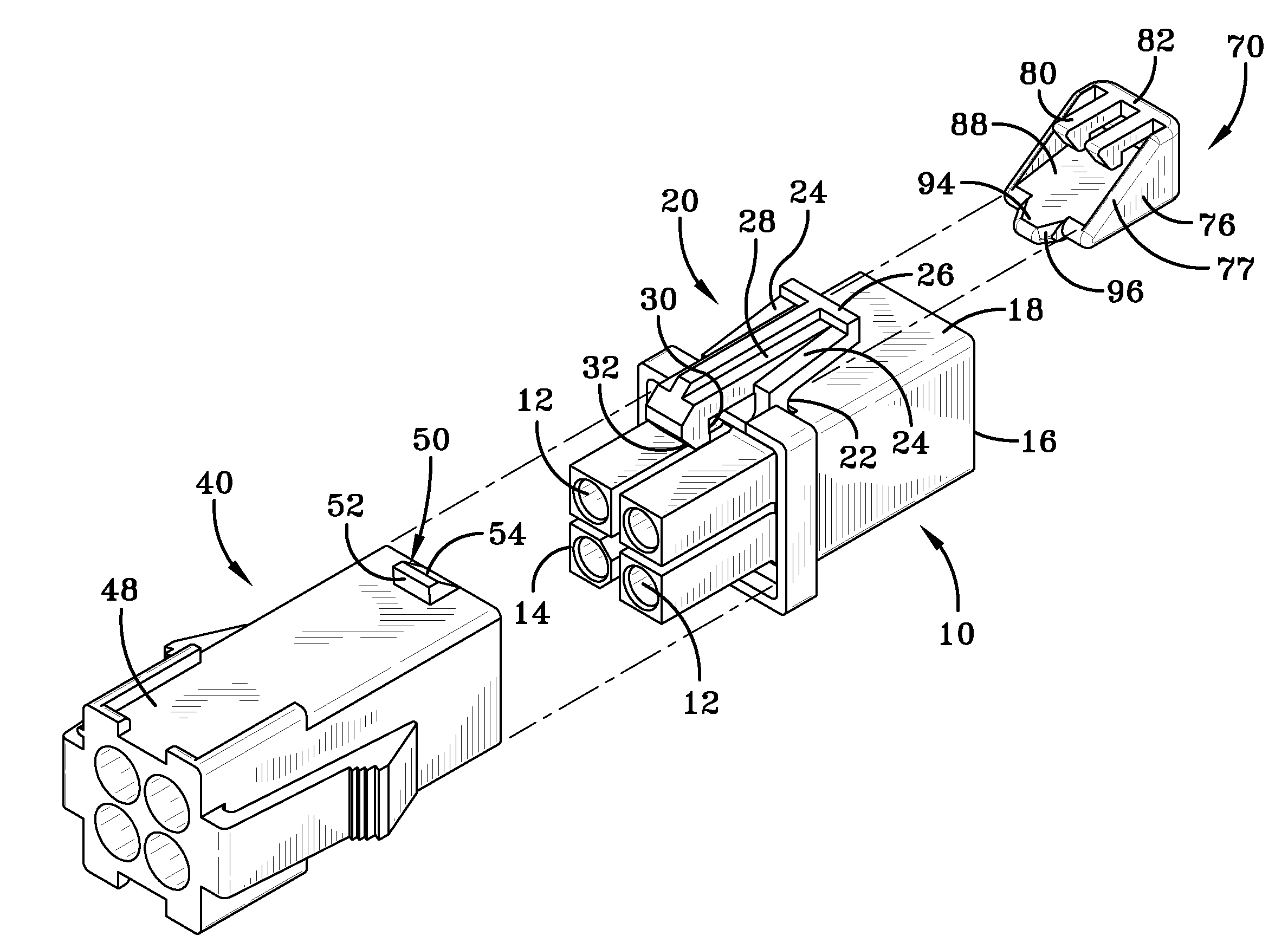
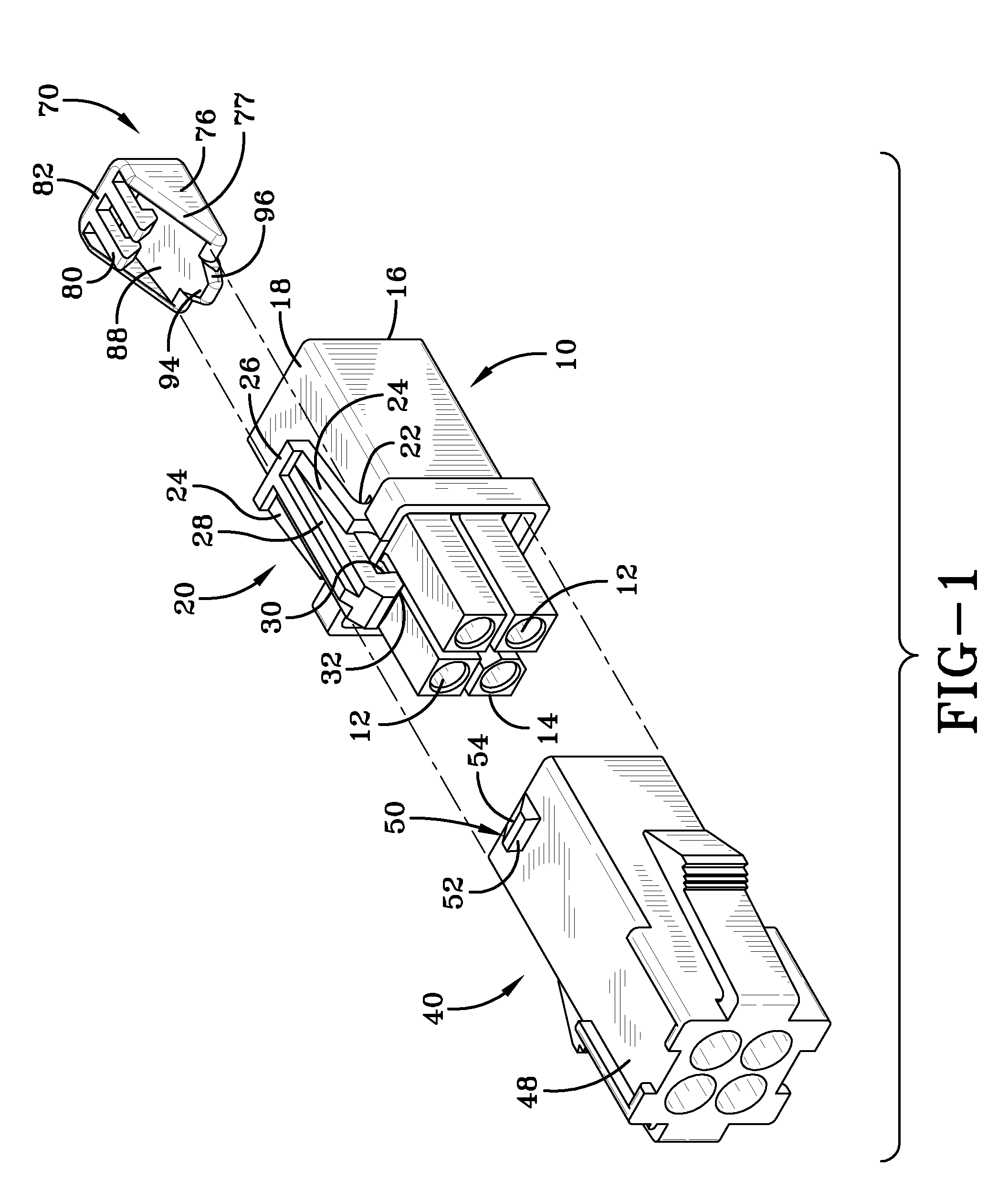
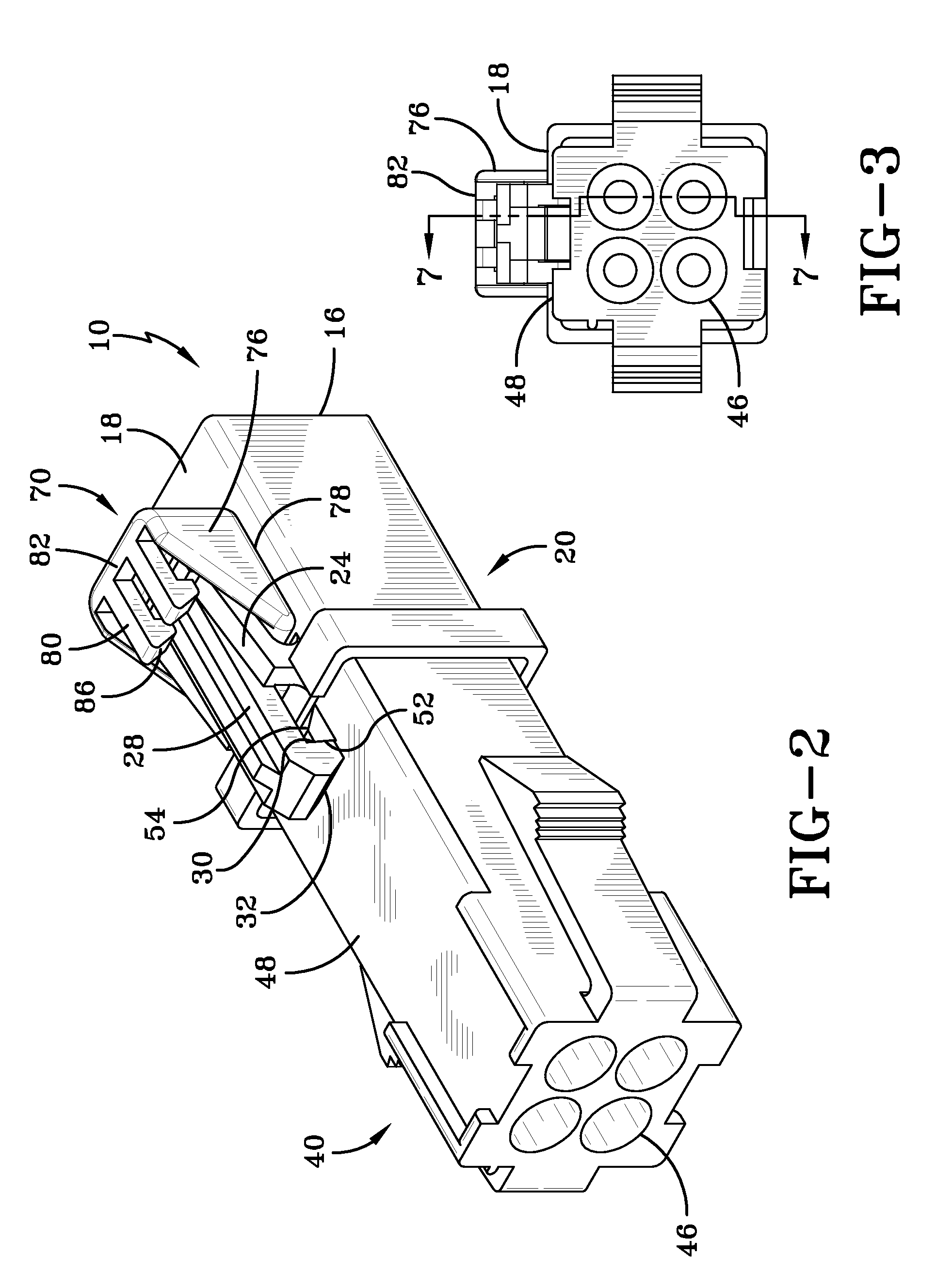
[0020]With reference to FIGS. 1, 2, 3, 7, 8 and 9 a connector assembly has a male connector housing 10, a female connector housing 40 and a latch securing member 70. The male connector housing 10 is a dielectric body which has a plurality of terminal receiving cavities 12 extending therethrough from a front face 14 to a rear face 16. Each of the cavities 12 is shown to have a cylindrical cross-section as it enters the rear face, although other cross-sectional shapes are encompassed within the scope of the invention. Pin type terminals (not shown) are insertable into the cavities 12. Extending from a side wall 18 is a latch member 20. In the configuration shown, the latch member 20 has two pivot members 22 which are attached to the sidewall 18. Two extension arms 24 extend from the pivot members 22 to a disengagement section 26. A latch arm 28 extends from the disengagement section 26 beyond pivot members 22 toward the front face 14 of the housing 10. A latching shoulder 30 and an in...


PUM


Abstract

A latch securing member for use in maintaining a first connector having at least one latching arm in latching engagement with a second connector having at least one latch projection. The latch securing member has an inclined member which extends from proximate a front face to a rear wall, with the inclined member being positioned proximate a bottom wall at the front face and inclined toward a top surface. At least one securing arm extends from the rear wall toward the front face and is positioned proximate the top surface. The inclined member is positioned to cooperate with the latching arm of the first connector to prevent the latching arm from disengagement from the latching projection of the second connector. The securing arm cooperates with the latching arm to maintain the latch securing member in position relative to the latching arm.

Description

FIELD OF THE INVENTION[0001]The present invention relates to an electrical connector having matable connector halves that are latched together. More particularly, the invention relates to a latch securing member that cooperates with the latch of at least one connector half to prevent the unwanted disengagement of the connector halves.BACKGROUND OF THE INVENTION[0002]Electrical connectors having connector position assurance members (CPA) or other means to prevent disengagement of locking latches are known in the industry. One such electrical connector is disclosed in U.S. Pat. No. 4,746,306. This connector has dielectric connector bodies that are coupled and locked together by a resilient lock member of one connector body which snaps past and engages a lock member of the other connector body. The resilient lock member includes a slot that extends through one end and a lock shoulder that faces the opposite end thereof. The other lock member includes a lock shoulder and a loop that pas...

Claims


Application Information

Patent Timeline
Patent Type & Authority Patents(United States)
IPC IPC(8): H01R13/62
CPCH01R13/6272H01R13/639
Inventor JONES, JR., ROYAL CURTISWHITAKER, JR., ROY KENNETH
Owner TYCO ELECTRONICS LOGISTICS AG (CH)
Why Eureka
Try Eureka