Miniature RF calibrator utilizing multiple power levels

a power level and rf calibrator technology, applied in the direction of frequency measurement arrangement, instruments, therapy, etc., can solve the problems of large volume, large space occupation, and large volume of external bench top calibrators, and achieve the effect of reducing the number of field test instruments and reducing the number of calibrations

Inactive Publication Date: 2010-03-23
ANRITSU CO
View PDF5 Cites 18 Cited by
  • Summary
  • Abstract
  • Description
  • Claims
  • Application Information

AI Technical Summary

Benefits of technology

[0008]According to embodiments of the present invention, a calibrator is provided that can generate precise sine waves and not suffer the drawbacks of prior art devices.
[0009]The calibrator is a battery operated and provides two very precise sine wave outputs for use in calibration of amplitude or frequency measuring test equipment. With battery power, a line voltage is not required during testing. The calibrator further uses small light weight components, so it can be easily transported and used in a field test area, and will not use front panel space of an instrument being calibrated
[0012]The low pass filter then removes all of the harmonics of the square wave to provide a precise sine wave output. The low pass filter output is provided through an attenuator and blocking capacitor to an output terminal of the calibrator. Diode protection devices are provided to divert static discharge or high power input surges applied to the output connector. The overall combination of components can be built from light weight low power components that still provide the precise sine wave output. Miniature low power components allow the calibrator to be battery operated and stored as a calibration component after use.

Problems solved by technology

It may be undesirable, however, to use the front panel space which is typically in short supply on portable instrumentation.
An external bench top calibrator, further, is typically bulky and requires a wall plug in line voltage for operation.
The required line voltage may not be available for a field test instrument.

Method used


Image

  • Miniature RF calibrator utilizing multiple power levels
  • Miniature RF calibrator utilizing multiple power levels
  • Miniature RF calibrator utilizing multiple power levels

Examples


Embodiment Construction

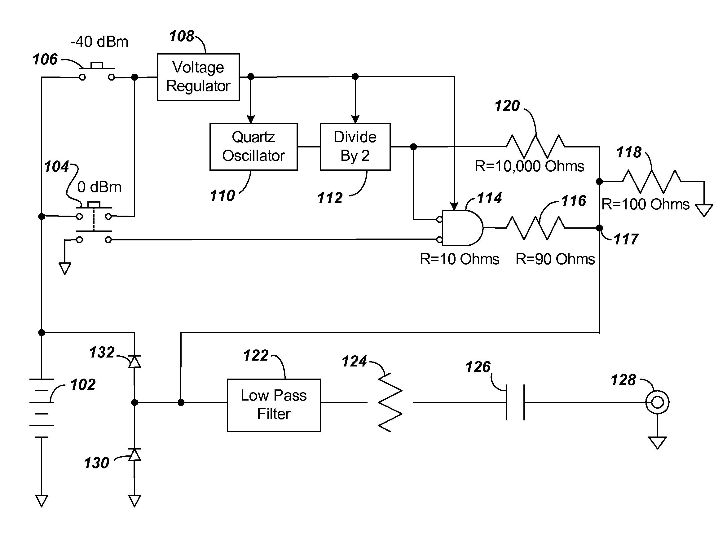
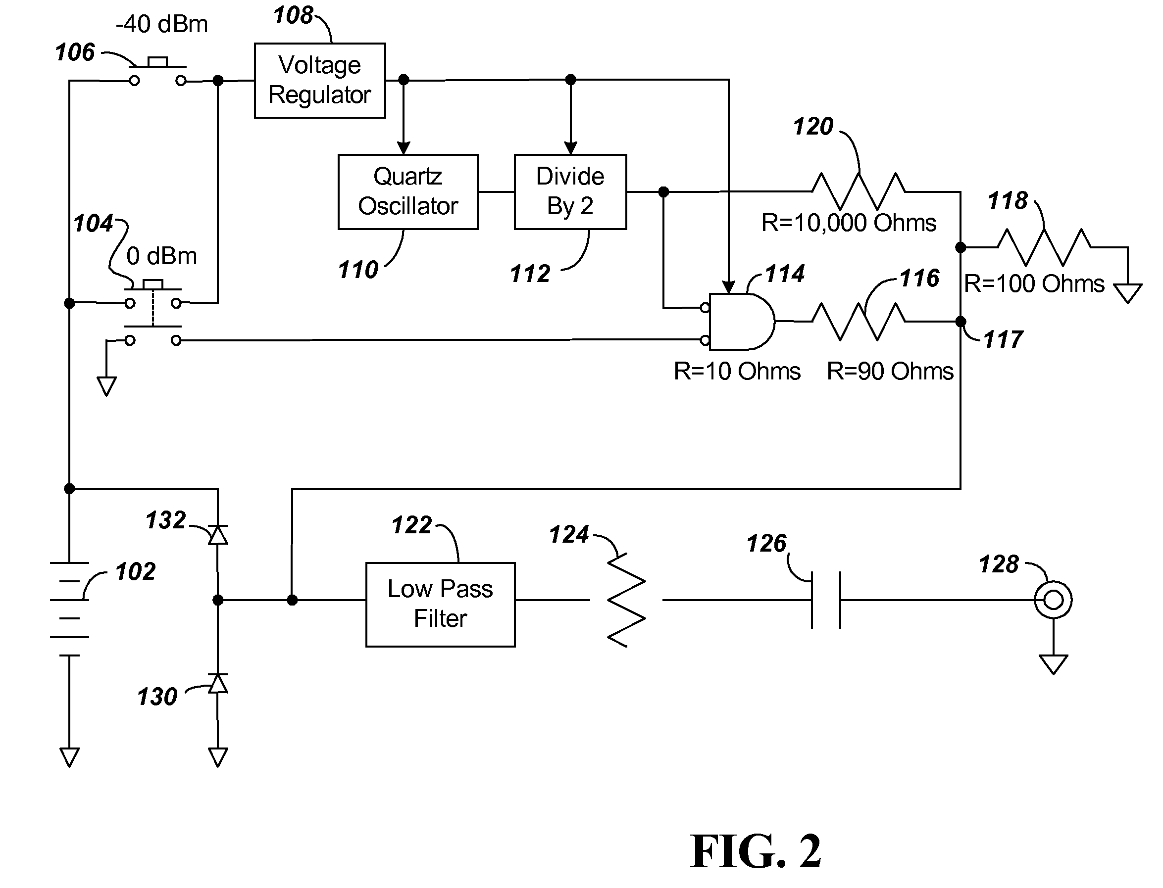
[0018]FIG. 2 shows a block diagram of a miniature RF calibrator according to embodiments of the present invention. The RF calibrator includes a battery 102 connected to two switches 104 and 106. The switch 104 provides an attenuation factor of 1 or 0 dBm, while the switch 6 provides an attenuation factor of 100 or −40 dBm. The purpose of the two power levels is to obtain a slope and offset for correction of the RF sensor in a test device being calibrated.

[0019]The output of the switches 104 and 106 are connected to a voltage regulator 8. The output of the voltage regulator 8 provides power driving a quartz oscillator 10, a divide by two flip flop 12, and a two input AND gate. The oscillator 10 provides a highly accurate frequency at twice the output frequency to the divide by two flip flop 12. The square wave output has its amplitude controlled by the precision temperature corrected DC voltage regulator 108 and its frequency controlled by the quartz temperature corrected oscillator ...


PUM


Abstract

A small light-weight battery operated calibrator device provides a precise sine wave output for use in calibration of test equipment, such as a RF Power Meter or a Spectrum Analyzer. The calibration device includes two power levels, one −40 dBm and one 0 dBm. The purpose of the two power levels is to obtain a slope and offset for correction of the RF power measuring device being calibrated. Operation indication LED lights are provided to indicate which of the two powers are in use, and if battery power is below acceptable levels. Miniature low power components including a crystal oscillator and a divide by 2 integrated circuit that generates a precise square wave and a low pass filter for converting the square wave into a precise sine wave allows the calibrator to be battery operated and stored as a calibration component.

Description

BACKGROUND[0001]1. Technical Field[0002]The present invention relates to components used in the calibration or verification of absolute frequency and amplitude measuring test equipment. More particularly the present invention relates to a highly accurate sine wave generation circuit used in calibrating or verifying the accuracy of test equipment such as RF power meters and spectrum analyzers.[0003]2. Related Art[0004]Existing calibration devices that can generate precise sine waves are typically provided internal to the instrument being calibrated, or as an external attachment. The internal RF calibrator in a test device typically has one power level and is accessible using the front panel space on the instrument. It may be undesirable, however, to use the front panel space which is typically in short supply on portable instrumentation. An external bench top calibrator, further, is typically bulky and requires a wall plug in line voltage for operation. The required line voltage may ...

Claims


Application Information

Patent Timeline
Patent Type & Authority Patents(United States)
IPC IPC(8): G01R35/00
CPCH03L1/022
Inventor BRADLEY, DONALD ANTHONY
Owner ANRITSU CO
Why Eureka
Try Eureka