
Method and apparatus for tuning an optical delay line

a delay line and optical technology, applied in the field of optical delay lines, can solve the problems of affecting the accuracy of tuning the delay, the heat produced by the heater b>100/b> is not well confined, and the power consumption and operating speed of the delay line are negatively affected, so as to achieve the effect of minimal crosstalk

Inactive Publication Date: 2010-03-23
INT BUSINESS MASCH CORP
View PDF10 Cites 5 Cited by
  • Summary
  • Abstract
  • Description
  • Claims
  • Application Information

AI Technical Summary

Benefits of technology

[0008]The present invention is a method and an apparatus for tuning an integrated optical delay line. In one embodiment, an optical delay line includes at least one ring resonator in which light is guided or is confined and at least one heater positioned laterally from the ring resonator. The heater produces heat in a localized area, allowing for the tuning of individual delay elements with minimal crosstalk.

Problems solved by technology

A common problem with waveguide structures like the waveguide structure 100, however, is that the heat produced by the heater 100 is not well confined.
This negatively impacts the power consumption and operating speed of the delay line.
In addition, the ability to accurately tune the delay, which is advantageous in most optical delay line applications, has not been satisfactorily addressed in existing optical delay lines.
Finally, material requirements (among other parameters) make integration of conventional optical delay lines with other passive and active photonic devices and electric circuits impractical.

Method used


Image

  • Method and apparatus for tuning an optical delay line
  • Method and apparatus for tuning an optical delay line
  • Method and apparatus for tuning an optical delay line

Examples


Embodiment Construction

[0015]In one embodiment, the present invention is a method and apparatus for tuning an optical delay line. Embodiments of the present invention provide a compact, accurately tunable optical delay line that allows accurate tuning of the delay with a minimal number of control signals.

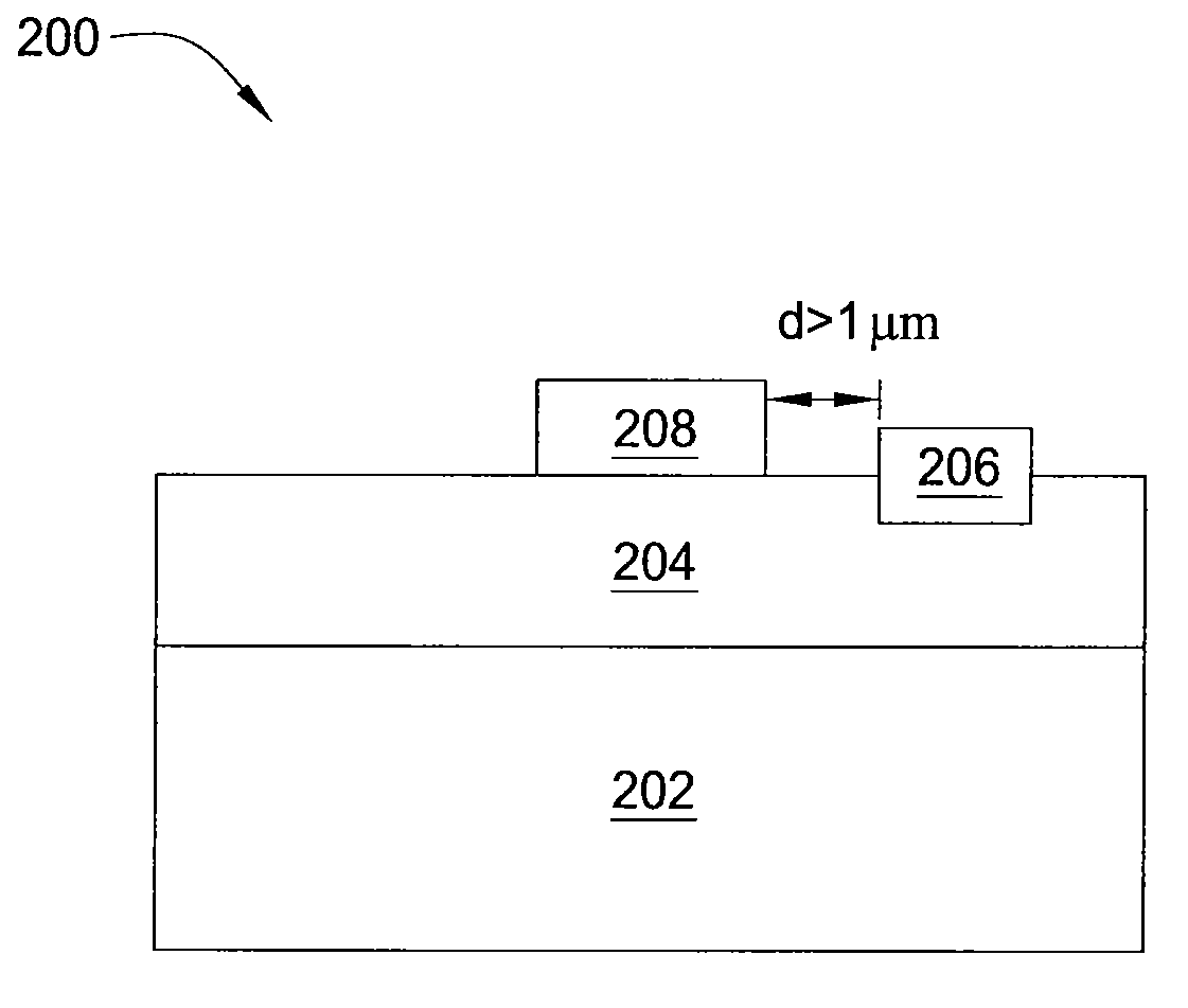
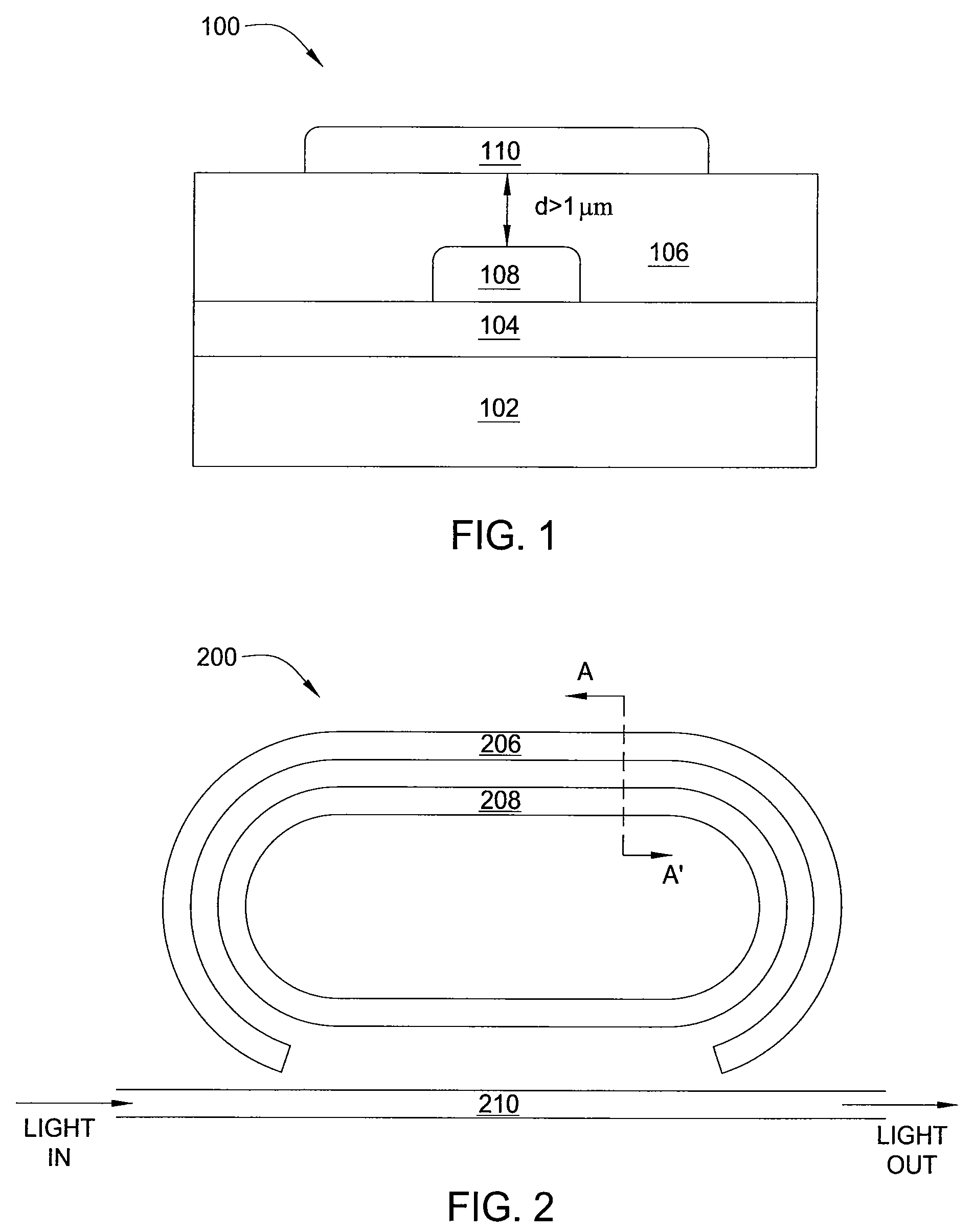
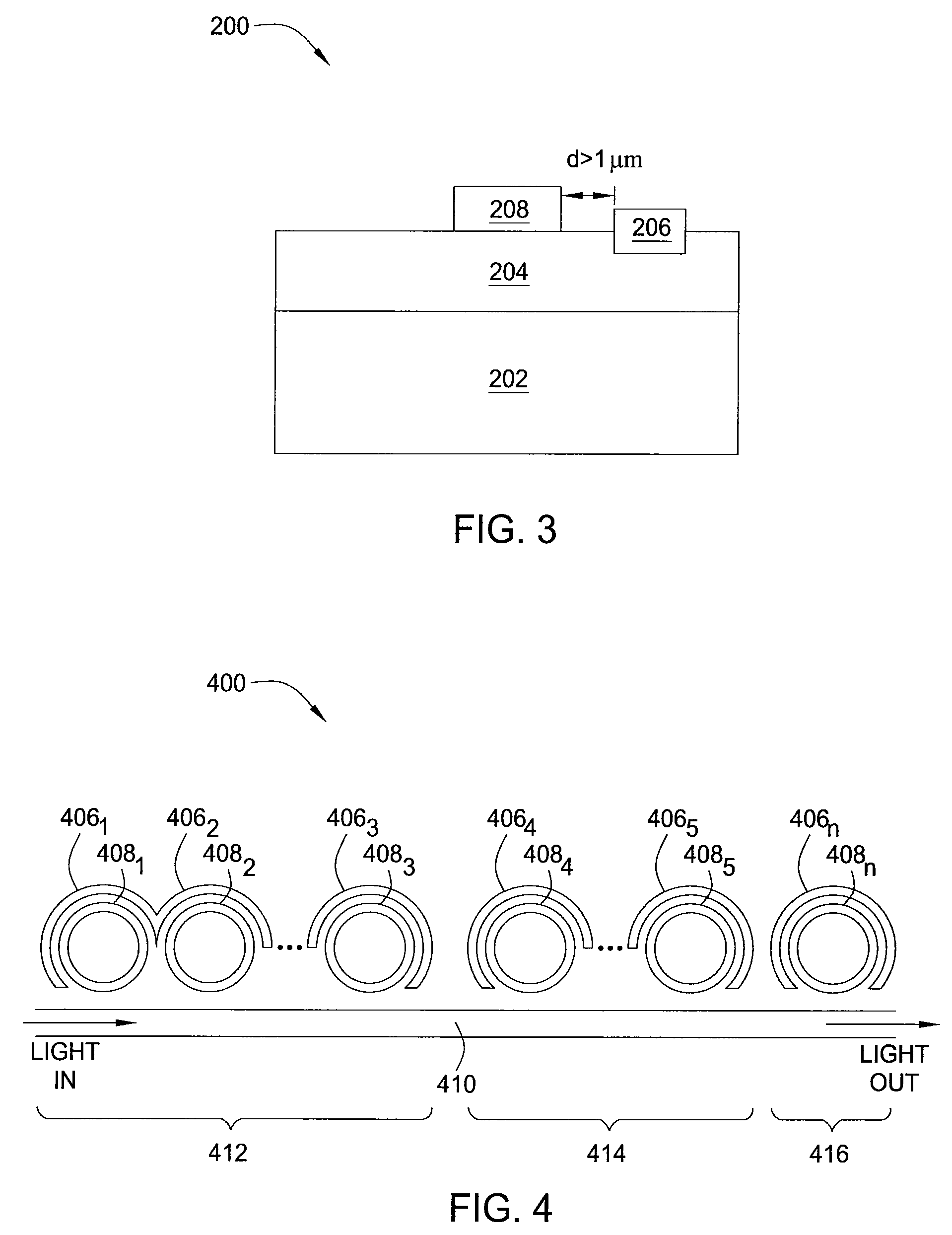
[0016]FIG. 2 is a cross-sectional view illustrating one embodiment of a tunable delay line 200 comprising a single resonantly enhanced delay element, according to the present invention. FIG. 3 is a cross sectional view illustrating the tunable delay line 200 of FIG. 2 along line A-A′. In one embodiment, the delay line 200 is a silicon-on-insulator (SOI) structure. Referring simultaneously to FIGS. 2 and 3, the delay line 200 comprises a substrate 202, a buried oxide layer 204, a heater 206, a ring resonator 208 and a strip waveguide 210.

[0017]In one embodiment, the substrate 202 is formed of material having good thermal conductivity, such as silicon. The buried oxide layer 204 is formed on the substrate 2...


PUM


Abstract

The present invention is a method and an apparatus for tuning an optical delay line. In one embodiment, an optical delay line includes at least one ring resonator in which light is guided or is confined and at least one heater positioned laterally from the ring resonator. The heater produces heat in a localized area, allowing for the tuning of individual delay elements with minimal crosstalk.

Description

REFERENCE TO GOVERNMENT FUNDING[0001]This invention was made with Government support under Contract No. N00014-04-C-0455 awarded by Defense Advanced Research Projects Agency (DARPA). The Government has certain rights in this invention.BACKGROUND[0002]The invention relates generally to optics, and relates more particularly to optical delay lines.[0003]Optical delay lines are used a variety of applications including optical communications, radio-frequency (RF) photonics, future optical interconnects and the like. FIG. 1 is a cross-sectional view illustrating a waveguide structure 100 with tuning pads, such as may be incorporated in a conventional integrated optical delay line. The waveguide structure 100 comprises a substrate 102, a first oxide layer 104, a second oxide layer 106, a waveguide 108 and a heater 110. As illustrated, the waveguide 108 is disposed between the first oxide layer 104 and the second oxide layer 106, while the heater 110 is disposed on the second oxide layer 10...

Claims


Application Information

Patent Timeline
Patent Type & Authority Patents(United States)
IPC IPC(8): G02B6/42
CPCG02B6/12007G02B6/2861
Inventor HAMANN, HENDRIKVLASOV, YURII A.XIA, FENGNIAN
Owner INT BUSINESS MASCH CORP
Learn More