Connector and device for wireless transmission of data and power

a technology of wireless transmission and connecting device, which is applied in the direction of telemetric patient monitoring, diagnostic recording/measuring, transportation and packaging, etc., and can solve problems such as jeopardizing functionality or safety

Active Publication Date: 2019-12-17
KONINKLJIJKE PHILIPS NV
View PDF18 Cites 6 Cited by
  • Summary
  • Abstract
  • Description
  • Claims
  • Application Information

AI Technical Summary

Benefits of technology

[0009]It is an object of the present invention to provide a reliable and low-cost connector and a device for wireless transmission of data and power between separate devices.
[0024]The advantages of the present invention thus include that no antenna switching means is required, but seamless switching between connected and unconnected state is possible. Less RF bandwidth occupation is needed, and minimal crosstalk between measurement, powering and radio appears. Magnetic powering is thus only enabled when efficient coupling is given. Finally, power saving of radio transmission is achieved when the connector is mechanically connected to a counterpart connector.
[0030]Various designs of the RF antenna are generally possible. Preferred antenna designs include that the RF antenna is shaped in the form of a stripe, ring, planar inverted F or planar folded dipole. Further, the RF antenna is preferably arranged rotational symmetrically, which avoids the need for a predetermined rotational positioning of the connector with respect to a counterpart connector when connecting them. In an exemplary implementation a quarter wavelength planar inverted F-antenna may be used.
[0032]The flux concentrator may comprise a core shaped in the form of a C or E and / or may be arranged rotational symmetrically, which also supports avoiding the need for a predetermined rotational positioning of the connector with respect to a counterpart connector when connecting them.

Problems solved by technology

Wireless powering can also be used in harsh environments where corrosion or moisture might jeopardize functionality or safety when galvanic contacts are used.

Method used


Image

  • Connector and device for wireless transmission of data and power
  • Connector and device for wireless transmission of data and power
  • Connector and device for wireless transmission of data and power

Examples


first embodiment

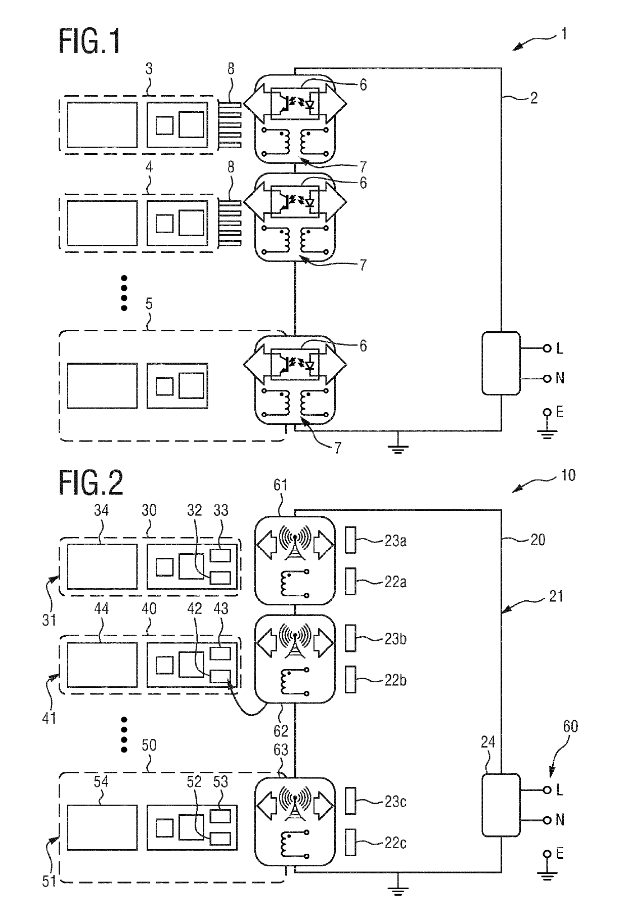
[0082]FIG. 2 shows a schematic diagram of a system 10 including a plurality of devices 20, 30, 40, 50 according to the present invention. According to the embodiment the devices 30, 40, 50 (e.g. representing measurement modules 30, 40, 50) are each connected in a wireless manner to the central processing unit 20, e.g. a patient monitor. Measurement modules, for instance in a patient monitoring system, are connected to the central processing unit 20 by individual magnetically coupled power transfer and near field contactless data transfer (whereby there may also be devices which only provide means for either magnetically coupled power transfer or near field contactless data transfer). This flexible architecture complies with the following applications of physiological measurements: measurement modules located on the main board (i.e. in the central processing unit 10), modular ‘plug-in’ measurement modules, measurement modules located in a mobile measurement server connected to the ce...

second embodiment

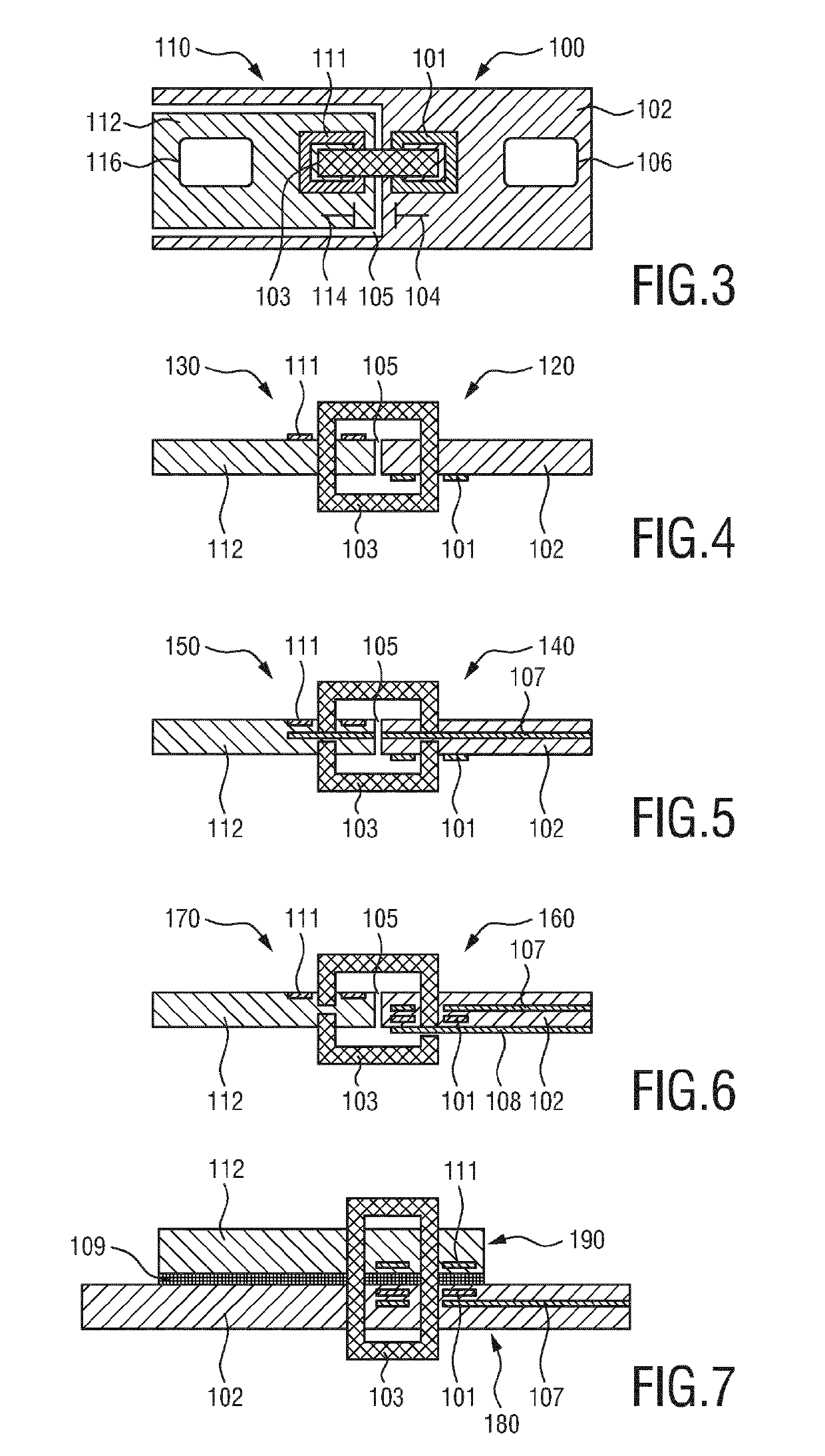
[0092]FIG. 4 schematically shows a cross-sectional view of a connector 120, 130 for use in the system according to the present invention providing isolated measurement on the mainboard of the central processing unit. The coils 101, 111 are located on different surfaces of the respective PCB 102, 112 and are magnetically coupled via a flux concentrator 103.

[0093]Obviously, many variations on this approach are feasible. FIG. 5 schematically shows a cross-sectional view of a third embodiment of a connector 140, 150 for use in the system according to the present invention. In this embodiment a third in-between layer 107 is provided, which is arranged within the PCB 102, in vertical direction, on a height level in between the coil 101 and the coil 111. The third in-between layer 107 is connected to ground to reduce stray capacitive coupling between the coils 101, 111. Further layers, such as another ground layer 108, may be added for EMC reasons, as shown in FIG. 6 depicting a fourth emb...

fifth embodiment

[0094]FIG. 7 schematically shows a cross-sectional view of a connector 180, 190 for use in the system according to the present invention. In this embodiment the measurement PCB 112 is located on top of the mainboard PCB 102 with an insulation foil 109 in between and magnetically coupling via the flux concentrator 103.

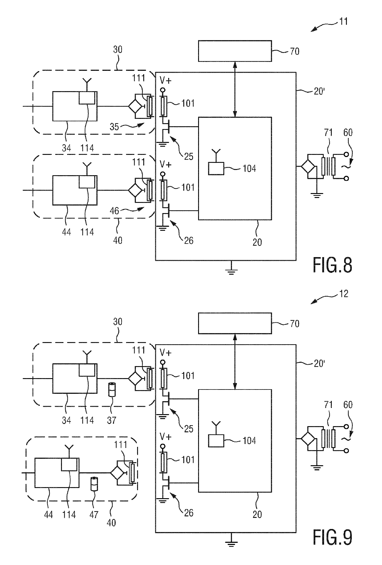
[0095]In still another variation of one of the above described embodiments the secondary coil may be integrated on the die or in the package of an ASIC, which comprise the electronic circuitry of the measurement.

[0096]Preferably, the main microprocessor on the central processing unit controls or drives the primary coil of the transformer. The AC voltage of the secondary coil is rectified and stabilized to supply the measurement module. This approach may make use of the Qi standard (or other standard) of wireless charging, and the arrangement and construction of the components can generally be made to fulfill requirements of one or more of these standards (e.g. the coils...


PUM


Abstract

The present invention relates to a connector for wireless transmission of data and / or power between separate devices comprising such a connector of a system, in particular of a patient monitoring system, said separate devices comprising such a connector. The connector comprises a data transmission unit (271) arranged for transmitting data to and / or receiving data from another device of the system having a counterpart connector, a magnetic coupling unit (272) for transmitting power to and / or receiving power from another device of the system having a counterpart connector by use of inductive coupling, a detection unit (273) for detecting the strength of magnetic coupling between the magnetic coupling unit and a magnetic coupling unit of a counterpart connector, and a control unit (274) for switching the data transmission unit into a low-power mode and / or for enabling the magnetic coupling unit, if the detected magnetic coupling is above a first threshold and / or its increase is above a second threshold, and for switching the data transmission unit into a high-power mode and / or for disabling the magnetic coupling unit, if the detected magnetic coupling is below a third threshold and / or its decrease is above a fourth threshold.

Description

CROSS REFERENCE TO RELATED APPLICTIONS[0001]This application is the U.S. National Phase application under 35 U.S.C. § 371 of International Application No. PCT / EP2016 / 070026, filed Aug. 25, 2016, published as WO 2017 / 036895 on Mar. 9, 2017, which claims the benefit of European Patent Application Number 15183599.8 filed Sep. 3, 2015. These applications are hereby incorporated by reference herein.FIELD OF THE INVENTION[0002]The present invention relates to a connector for wireless transmission of data and power between separate devices comprising such a connector of a system, in particular of a patient monitoring system, said separate devices comprising such a connector. Further, the present invention relates to a device for wireless transmission of data and power between the device and another device.BACKGROUND OF THE INVENTION[0003]Wireless charging or powering of devices in general is an established technique that is convenient to users. Wireless powering can also be used in harsh e...

Claims


Application Information

Patent Timeline
Patent Type & Authority Patents(United States)
IPC IPC(8): H02J50/10H02J5/00H04B5/00H02J7/00A61B5/00
CPCH04B5/0075H04B5/0031H02J5/005H04B5/0037H04B5/0081H02J50/10H04B5/0056A61B5/002H02J2007/0001A61B2560/0214H04B5/0012H02J7/00045H02J2310/23
Inventor KAHLMAN, JOSEPHUS ARNOLDUS HENRICUS MARIA
Owner KONINKLJIJKE PHILIPS NV
Why Eureka
Try Eureka