
Crosstalk reduction in receiver inductive loop using capturing loop in transmitting inductive loop

a technology of inductive loop and inductive loop, which is applied in the field of digital isolators, can solve the problems of insufficient insufficient in many instances of capacitive isolation digital isolators, so as to achieve less crosstalk and improve manufacturing cost

Active Publication Date: 2020-01-02
TEXAS INSTR INC
View PDF0 Cites 2 Cited by
  • Summary
  • Abstract
  • Description
  • Claims
  • Application Information

AI Technical Summary

Benefits of technology

The patent describes a way to reduce interference between channels in a multi-channel digital isolator. The design uses two inductive loops, one for transmitting data and one for receiving data. The size of the receiving loop is smaller and opposite in sign to the main loop in the transmitting channel. This arrangement reduces the likelihood of crosstalk, making it more dense and cost-effective to manufacture. In summary, the design helps to isolate the data channels and minimize interference.

Problems solved by technology

However, there are many circumstances where opto-couplers do not provide adequate performance.
However, modern ultralow power requirements have made even the lower power levels of capacitive isolation digital isolators insufficient in many instances.
While this is not an issue for capacitive isolation digital isolators, this bi-directional configuration results in the potential for undesired crosstalk or cross-coupling in an inductive loop or transformer digital isolator.
Another approach stacks the receive and transmit inductive loops vertically, but this makes manufacturing much more challenging.

Method used


Image

  • Crosstalk reduction in receiver inductive loop using capturing loop in transmitting inductive loop
  • Crosstalk reduction in receiver inductive loop using capturing loop in transmitting inductive loop
  • Crosstalk reduction in receiver inductive loop using capturing loop in transmitting inductive loop

Examples


Embodiment Construction

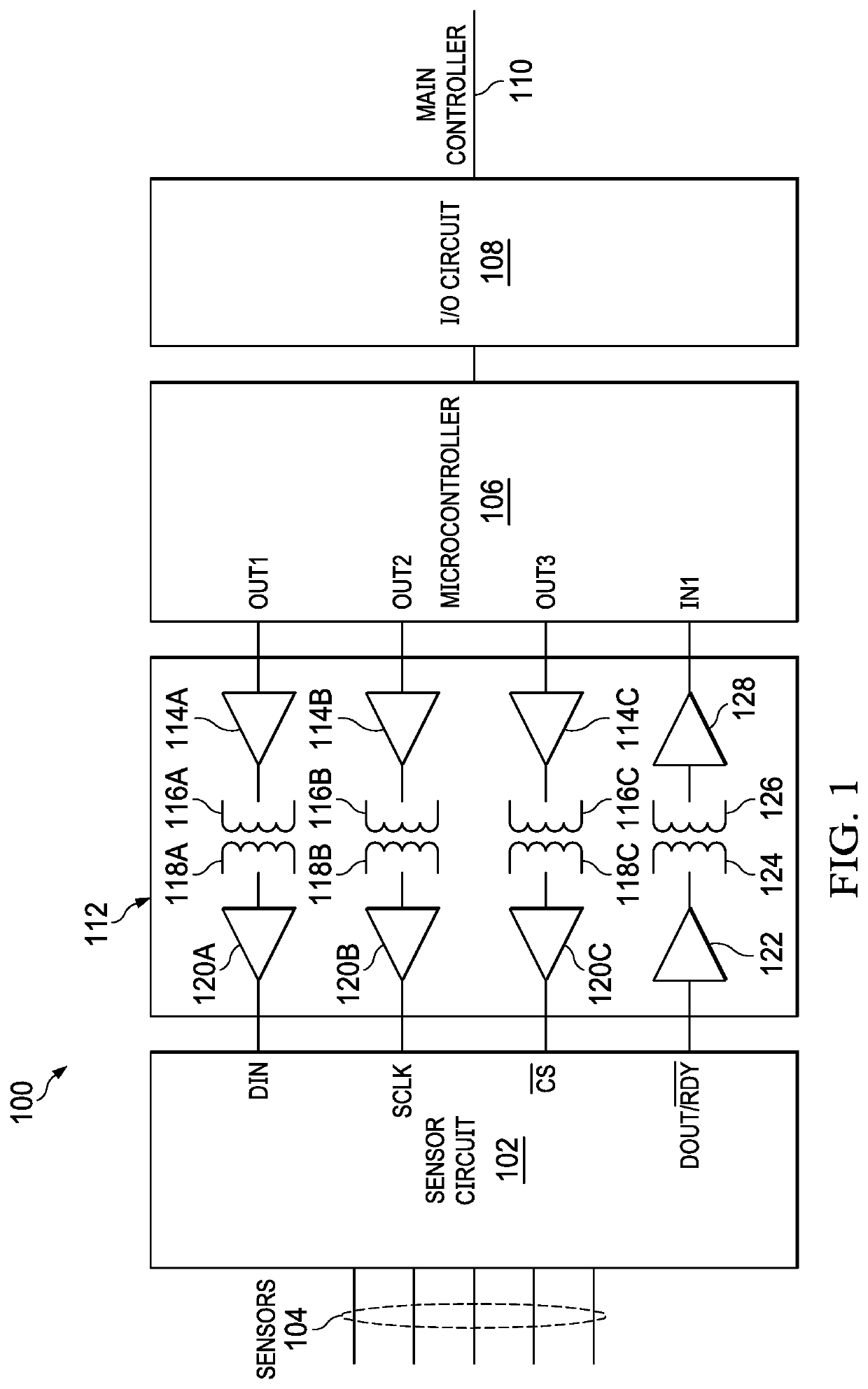
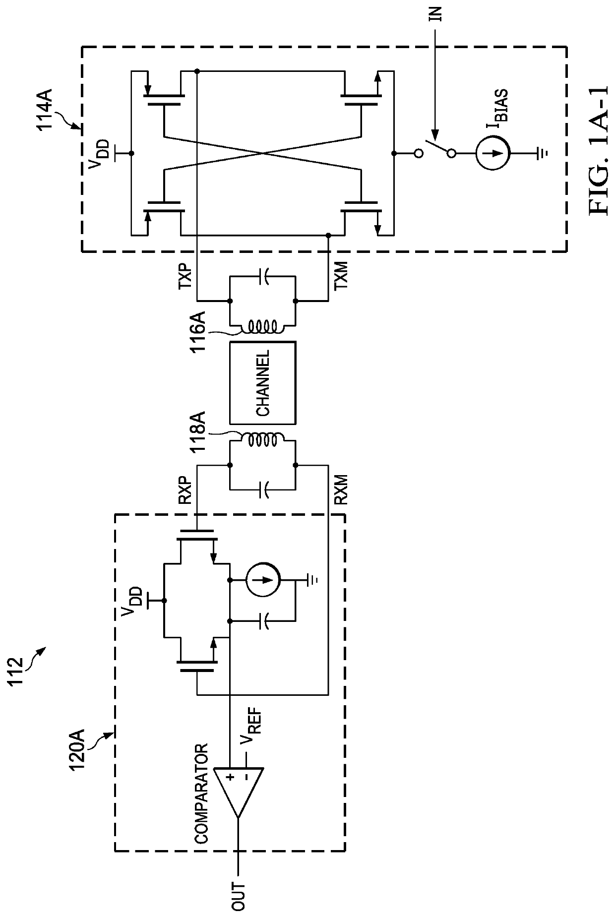
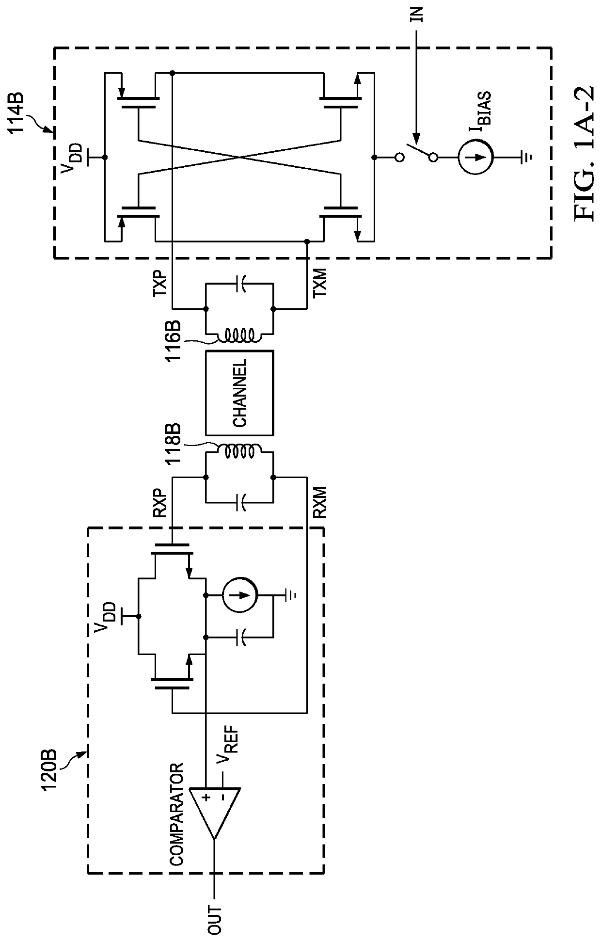
[0018]Referring now to FIG. 1, an example use of a digital isolator is provided. A sensor module 100 includes a sensor circuit 102 which is connected to various sensors 104 that are being monitored. A microcontroller 106 provides the intelligence for the sensor module 100. An input / output (I / O) circuit 108 is connected to the microcontroller 106 and to a main controller no to provide the sensor readings to the main control system. The sensor circuit 102 and the microcontroller 106 are connected by a digital isolator 112. The digital isolator 112 is a four channel device with three channels being connected to transfer data from the microcontroller 106 to the sensor circuit 102 and one channel connected to transfer data from the sensor circuit 102 to the microcontroller 106. The digital isolator 112 is an inductive isolation device which uses inductive loops to transfer the signal across the isolation barrier. Receiver circuitry 114A receives the output signal from the OUT1 output of ...


PUM


Abstract

An inductively coupled multi-channel digital isolator where the transmitter and receiver inductive loops of a given channel are coplanar. In the case where two adjacent channels flow data in opposite directions, the receiver inductive loops of a given channel include a large, generally conventional loop portion and a small loop portion that is located inside the transmitter inductive loops of the adjacent channels. The sizes of the small loop portion and the conventional loop portion are generally in the ratio of the magnetic flux in the conventional loop portion to the magnetic flux in the transmitter inductive loop. This size relationship results in the voltage of the small loop portion being very close but opposite in sign to the voltage in the conventional loop portion. As a result, there is minimal crosstalk from the transmitter inductive loop of one channel to the receiver inductive loop of the adjacent channel.

Description

BACKGROUND1. Field[0001]The field is digital isolators.2. Description of the Related Art[0002]Digital isolators are used to allow signal transfer between environments that must remain electrically isolated. The simplest form of a digital isolator is an opto-coupler. In an opto-coupler a signal is provided to drive a photodiode. A phototransistor is configured to receive the light emitted from the photodiode. Electrical isolation is provided between the photodiode and the phototransistor simply by an air gap through which the light passes. However, there are many circumstances where opto-couplers do not provide adequate performance. Therefore, another class of digital isolators has developed which utilize a capacitive isolation barrier. Effectively one plate of a capacitor is present on the input side and the other plate of the capacitor is present on the output side, with the capacitive isolation barrier separating the capacitor plates. Capacitive isolation digital isolators have lo...

Claims


Application Information

Patent Timeline
Patent Type & Authority Applications(United States)
IPC IPC(8): H04B3/32H04B1/10
CPCH04B1/10H04B3/32H04L25/026H04L25/0272
Inventor SHRIVASTAVA, KUMAR ANURAG
Owner TEXAS INSTR INC
Learn More