
Physiological measurement display

a technology of physiological measurement and display, applied in the field of physiological measurement display, can solve the problems of inability to match the design of the prior art to persons of different sizes, inability to accurately measure data, and inability to achieve auxiliary functions

Inactive Publication Date: 2010-03-23
G PULSE INT
View PDF21 Cites 53 Cited by
  • Summary
  • Abstract
  • Description
  • Claims
  • Application Information

AI Technical Summary

Benefits of technology

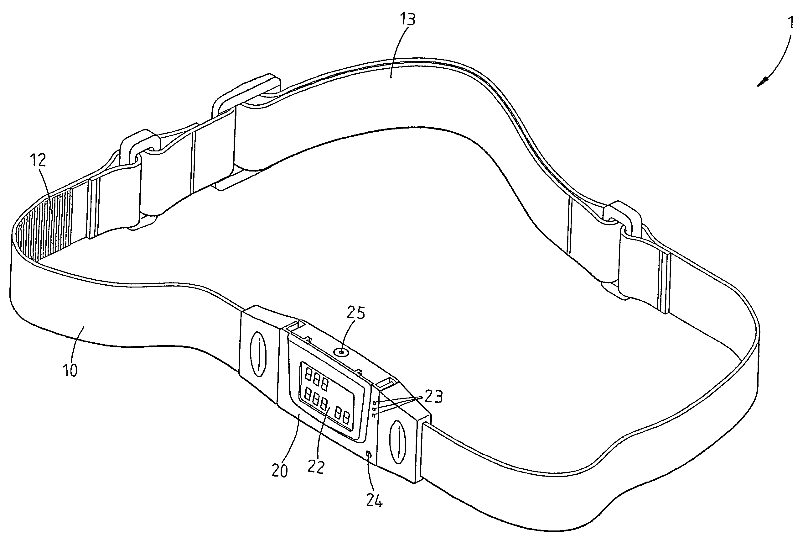
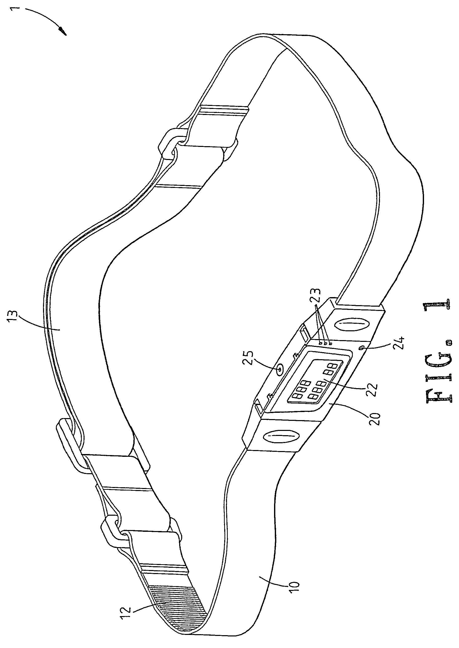
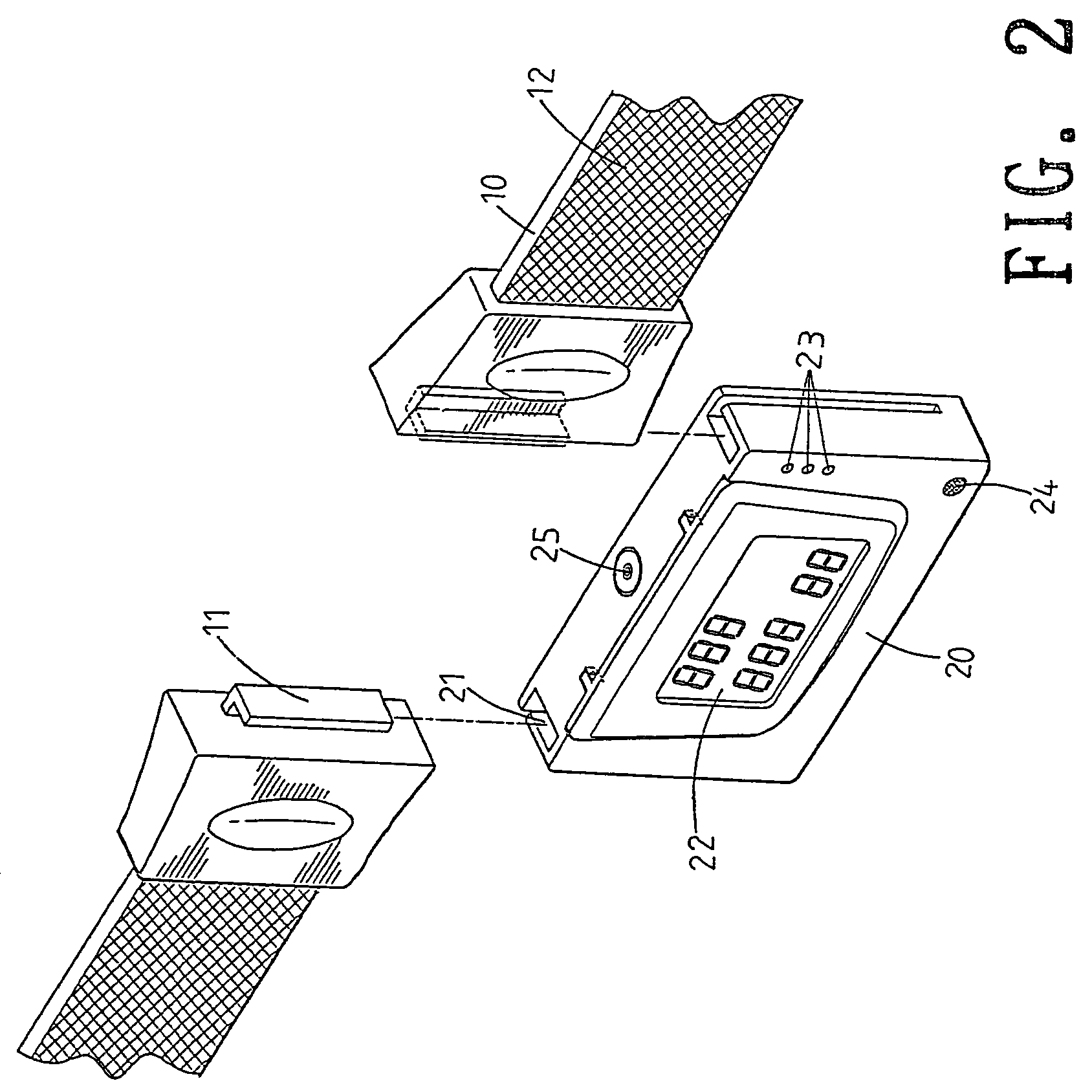
"The present invention is a physiological measurement display that can display various information to users. It has a display panel that can be turned for viewing at different angles. The display panel is connected to an electronic device that has conductive parts and can also have additional conductive elements. The electronic device can also have alarm lights, a speaker, or a level meter. The display panel can be securely attached to the electronic device using buckling grooves and buckles that are conductive. The invention provides a convenient and useful tool for monitoring physiological data."

Problems solved by technology

As a whole, it is not an ideal one, this is because the physiological measurement display has only one LCD display light to indicate whether it is operated normally, but no display is installed to show the data real time.
However this is inconvenient.
Furthermore in emergency, the physiological measurement unit of the prior art has no auxiliary function to alert the user or medical persons.
Furthermore, the design of the prior art can not be matched to persons of different sizes.
For those persons with great sizes, they are not suitable for wearing the physiological measurement unit and thus the measurement data are not accuracy.

Method used


Image

  • Physiological measurement display
  • Physiological measurement display
  • Physiological measurement display

Examples


second embodiment

[0026]Referring to FIG. 5, the physiological measurement display of the present invention is illustrated. In this embodiment, those identical to the above embodiment will not be further described herein. Only those different from above embodiment are described.

[0027]A backside of the electronic device 20 can be installed with an auxiliary conductive portion 26 which can perform the measurement in three points with the function of the conductive portion 12 so that the data has waveform and is more accurate.

third embodiment

[0028]Referring to FIGS. 6 to 10, the present invention is illustrated. In this embodiment, those identical to the above embodiment will not be further described herein. Only those different from above embodiment are described.

[0029]A backside of the electronic device 20 is adhered with a conductive rubber 27 and an upper end of the electronic device 20 is formed with two insertion holes 28.

[0030]Referring to FIG. 8, when using the present invention, the conductive rubber 27 and the conductive portions 12 are used to measure the body at three points so as to have information with waveform.

[0031]Referring to FIGS. 9 and 10, each insertion hole 28 of the electronic device 20 can be connected to an external conductive plate 29. The two external conductive plates 29, the two conductive portions 12 and the conductive rubber 27 are provided to measure the body information at four different points. Or the conductive plate 29 can be independently adhered to the body of the user for measurin...


PUM


Abstract

A physiological measurement display comprises: a strip having: at least one conductive portion at an inner side thereof; an electronic device connected to the conductive portion; the electronic device having at least one physiological measure unit; and a display panel at an outer side of the electronic device for displaying physiological data from the physiological measure unit. The electronic device is installed with a level meter, or alarm lights or a speaker. The display panel is pivotally installed to the electronic device and is turnable for viewing. Two ends of the electronic device have buckling grooves and two ends of the strip have buckles engageable to the buckling grooves. The buckles and buckling grooves are conductive. The electronic device is installed with an auxiliary conductive portion or a conductive rubber.

Description

FIELD OF THE INVENTION[0001]The present invention relates to a physiological measurement display, wherein physiological measurement display provides the function of display, alarm light, speaker and level meter so as to provide various information to users. Furthermore, the display is turnable so that the user can view the data at different views.BACKGROUND OF THE INVENTION[0002]The prior art physiological measurement strip has an elastic strip and a measure unit. The measure unit has a main body and a signal processor. The main body is made of flexible material and a backside thereof has two conductive cloths. The signal processor is installed at a front side of the main body and is electrically conductive to the conductive cloth. Two ends of the elastic strip are buckled to the main body for being worn on the breast of the user. The conductive cloths of the measure unit are adhered to the skin of the user so as to measure physiological data. The data is transferred to a computer, ...

Claims


Application Information

Patent Timeline
Patent Type & Authority Patents(United States)
IPC IPC(8): A61B5/04A61B5/00A61B5/05
CPCA61B5/00A61B5/6831A61B5/742A61B5/04085A61B5/282
Inventor JUAN, CHENG-PIN
Owner G PULSE INT
Learn More