Engine and a method of making same

a technology of internal combustion engine and engine body, which is applied in the direction of combustion engine, machine/engine, cylinder, etc., can solve the problems of fuel contamination of lubrication oil, consequential reduction of oil lubrication performance, and oil viscosity reduction, so as to reduce oil contamination

Active Publication Date: 2010-03-30
FORD GLOBAL TECH LLC
View PDF20 Cites 21 Cited by
  • Summary
  • Abstract
  • Description
  • Claims
  • Application Information

AI Technical Summary

Benefits of technology

[0011]According to a first aspect of the invention, there is provided an internal combustion engine having at least one cylinder for slidingly supporting a piston, the cylinder wall of the at least one cylinder of the engine being manufactured to provide at least one predetermined region having a low liquid storage volume so as to reduce oil contamination by fuel transfer past the piston. The at least one predetermined region is positioned within the respective cylinder in which fuel injected into the cylinder which is not combusted by the engine will contact the cylinder wall.
[0013]The engine may further comprise a reservoir for storing a supply of engine oil and the at least one predetermined region of the respective cylinder reduces the transfer of fuel from the respective cylinder to the reservoir.
[0020]The different pattern within each of the predetermined regions may comprise a smooth surface finish.
[0027]According to another aspect of the invention there is provided a method of manufacturing a cylinder for an internal combustion engine, the method including producing a cylinder wall with a required diameter and roundness and machining the cylinder wall to provide at least one predetermined region having a low liquid storage volume so as to reduce, in use, oil contamination by fuel transfer past a piston slidingly engaged with the cylinder. The at least one region is located on the cylinder wall such that, in use, any fuel injected into the cylinder which is not combusted by the engine will contact the cylinder wall substantially within the at least one region.

Problems solved by technology

It is also a requirement to regenerate an emission device of a spark ignited engine and in so doing it is a possibility that some unburned fuel may contact the cylinder walls and may result in the fuel contaminating the lubrication oil.
In any of these cases it is a problem that some of the fuel injected into each cylinder for regeneration purposes remains within the troughs in the surface of each cylinder wall and is subsequently transferred past the piston rings to the oil used to lubricate the engine.
The addition of this fuel to the oil can produce problems and, in particular, can lead to a reduction in oil viscosity with a consequential reduction in oil lubrication performance.

Method used


Image

  • Engine and a method of making same
  • Engine and a method of making same
  • Engine and a method of making same

Examples


first embodiment

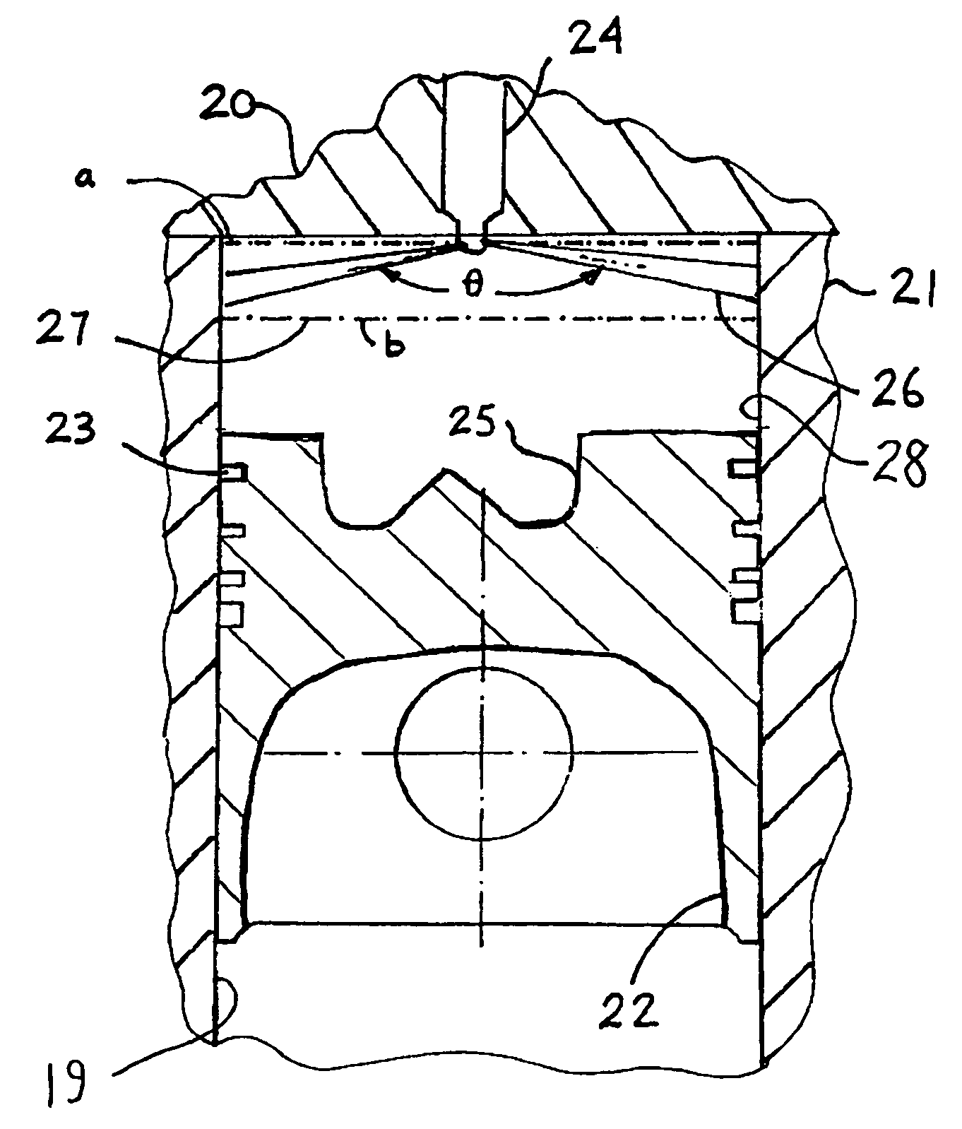
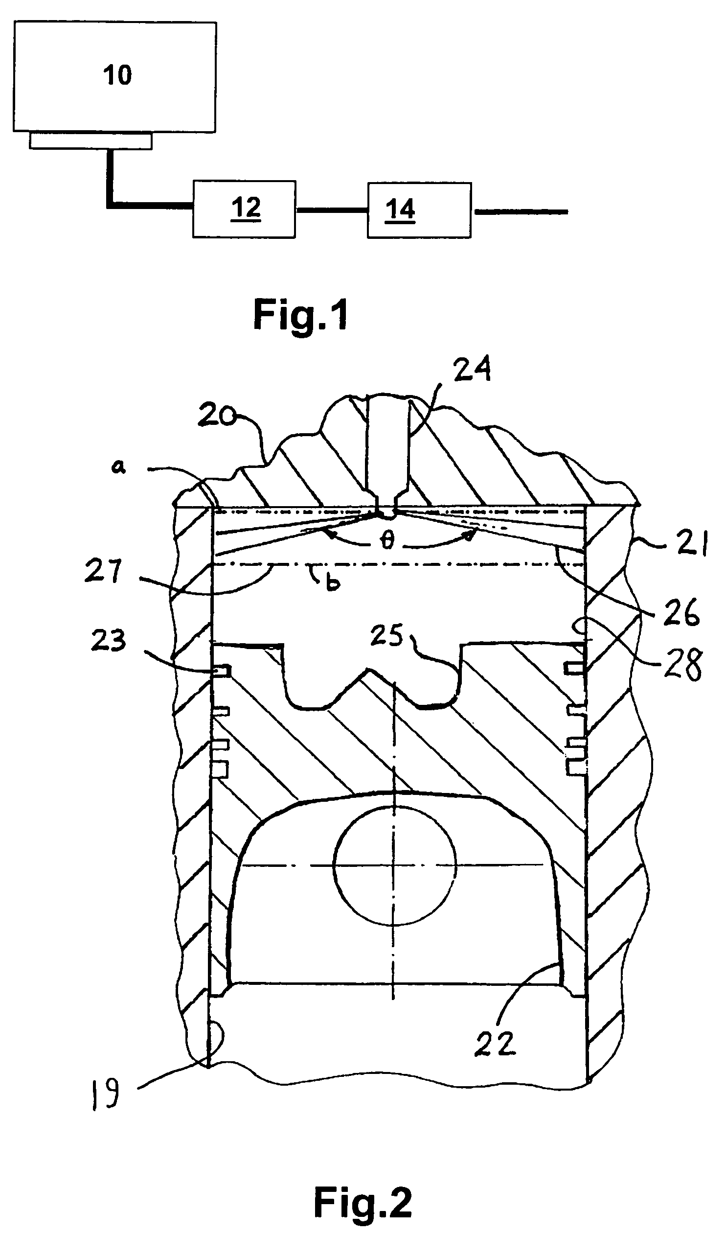
[0051]In the invention, the predetermined region is in the form of a single circumferentially extending band 27 having an upper edge ‘a’ and a lower edge ‘b’. Within this band 27, a different pattern is used to that used on other parts of the cylinder wall 28.

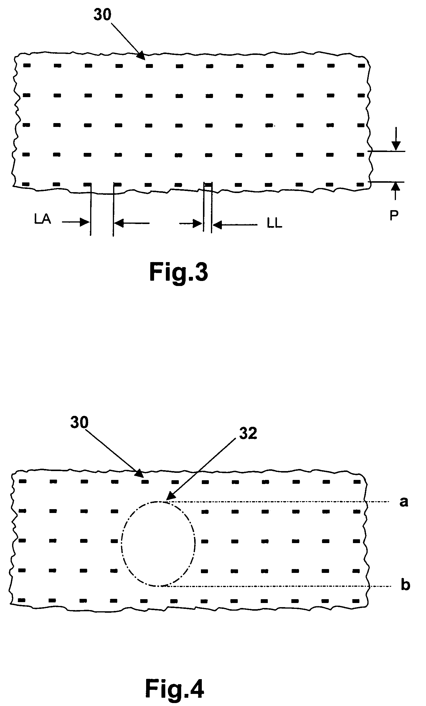
[0052]This different pattern can be of any suitable form; but in all cases, the average liquid storage capacity of the pattern per unit area of cylinder wall 28 is much lower than that for the first pattern.

[0053]In this embodiment, the different pattern (not shown) is formed by laser machining discrete pockets into the cylinder wall 28 within the band 27 which have less liquid storage capacity per unit area of cylinder wall 28 than the liquid storage capacity of the discrete pockets 30 forming the first pattern.

[0054]The positioning of the band 27 is chosen so that any unburned fuel coming into contact with the cylinder wall 28 is likely to contact the cylinder wall within the band 27. In particular the band 27 is positioned s...

second embodiment

[0055]Referring now to FIG. 4, there is shown the invention in which instead of a single predetermined region there are a number of circumferentially spaced regions 32 within each of which a different pattern to the first pattern is used. There are a like number of circumferentially spaced regions 32 as there are fuel jets 26.

[0056]Each of these regions 32 is surrounded by the first pattern and is positioned on the cylinder wall 28 such that one of the fuel jets 26 issuing from the injector nozzle 24 impinges against the cylinder wall 28 within the boundary of the region 32. The dimensions of each region 32 is sufficient that substantially all of any unburned fuel coming into contact with the cylinder wall 28 does so within the boundary of one of the regions 32. As before, the liquid storage capacity per unit area of the pattern used within each of the circumferentially spaced regions 32 is much lower than that used for the first pattern. The circumferentially spaced regions 32 are ...

third embodiment

[0059]In the case of the third embodiment shown in FIG. 5, there is more liquid or oil storage volume than that shown in FIG. 4, but much less than that for the surrounding first pattern. In this embodiment, the different pattern has a smooth surface finish having a surface texture of 0.05 to 0.2 μm RA in which a small number of discrete pockets 33 have been formed. In this case, the dimensions of each of the pockets 33, within each of the circumferentially spaced regions 32, is the same size as one of the pockets 30 in the first pattern; but, there are less pockets 33 per unit area in the pattern used within the circumferentially spaced regions 32 than in the first pattern. As shown, there are half as many pockets 33 used per unit area for the pattern used in the circumferentially spaced regions 32 compared to the first pattern but other ratios could be used. Once again, the first pattern can be of any suitable form; but, in this case is the same as that previously described with r...


PUM

PropertyMeasurementUnit
widthaaaaaaaaaa
widthaaaaaaaaaa
depthaaaaaaaaaa

Abstract

An internal combustion engine 10 is provided with cylinders 19 having a predetermined surface finish thereon comprising of at least two differing patterns. The first pattern is designed to provide a predetermined storage volume for oil used to lubricate a piston 22 which is slidingly engaged in the cylinder 19. The second pattern is different to the first pattern in that it provides little or no storage capacity for the oil. The second pattern is applied to the wall 28 of each cylinder 19 at one or more positions where impingement of unburned fuel against the cylinder wall 28 is to be expected. The reduced storage volume of the second pattern reduces the volume of unburned fuel that can be transferred from the cylinder 19 to the oil supply of the engine 10.

Description

FIELD OF THE INVENTION[0001]This invention relates to internal combustion engines and in particular to the manufacture of an internal combustion engine.BACKGROUND[0002]It is known that it is necessary to have a certain degree of roughness on each cylinder wall of an engine to retain oil used as a lubricant between the cylinder wall and the piston which is slidingly engaged within the respective cylinder. In practice, the surface of the cylinder wall comprises a number of peaks and troughs and the oil is stored within the troughs. It is further well known in the manufacture of internal combustion engines to use a honing process to produce a desired surface finish on the wall of each cylinder of the engine to provide such an oil retention surface.[0003]In recent years there has been an increased demand for the use of emission control devices on all engines used for automotive vehicles. In the case of spark ignition engines the use of NOx traps is becoming more common and in the case o...

Claims


Application Information

Patent Timeline
Patent Type & Authority Patents(United States)
IPC IPC(8): F02B5/00F02B5/02B23P13/02F02B3/06F02F1/00F02F1/18F02F1/20
CPCF02F1/20Y10T29/4927
Inventor CUMMING, BRIANKETCHER, DAVE
Owner FORD GLOBAL TECH LLC
Why Eureka
Try Eureka