Heat exchangers with turbulizers having convolutions of varied height

a technology of heat exchangers and convolutions, which is applied in the direction of tubular elements, lighting and heating apparatus, stationary conduit assemblies, etc., and can solve problems such as lowering the efficiency of heat transfer

Inactive Publication Date: 2010-03-30
DANA CANADA CORP
View PDF67 Cites 30 Cited by
  • Summary
  • Abstract
  • Description
  • Claims
  • Application Information

AI Technical Summary

Problems solved by technology

This causes the formation of a fluid bypass B (FIG. 3 of Gawve et al.) adjacent the edges of the fluid flow passage, which lowers the efficiency of heat transfer.

Method used


Image

  • Heat exchangers with turbulizers having convolutions of varied height
  • Heat exchangers with turbulizers having convolutions of varied height
  • Heat exchangers with turbulizers having convolutions of varied height

Examples


Embodiment Construction

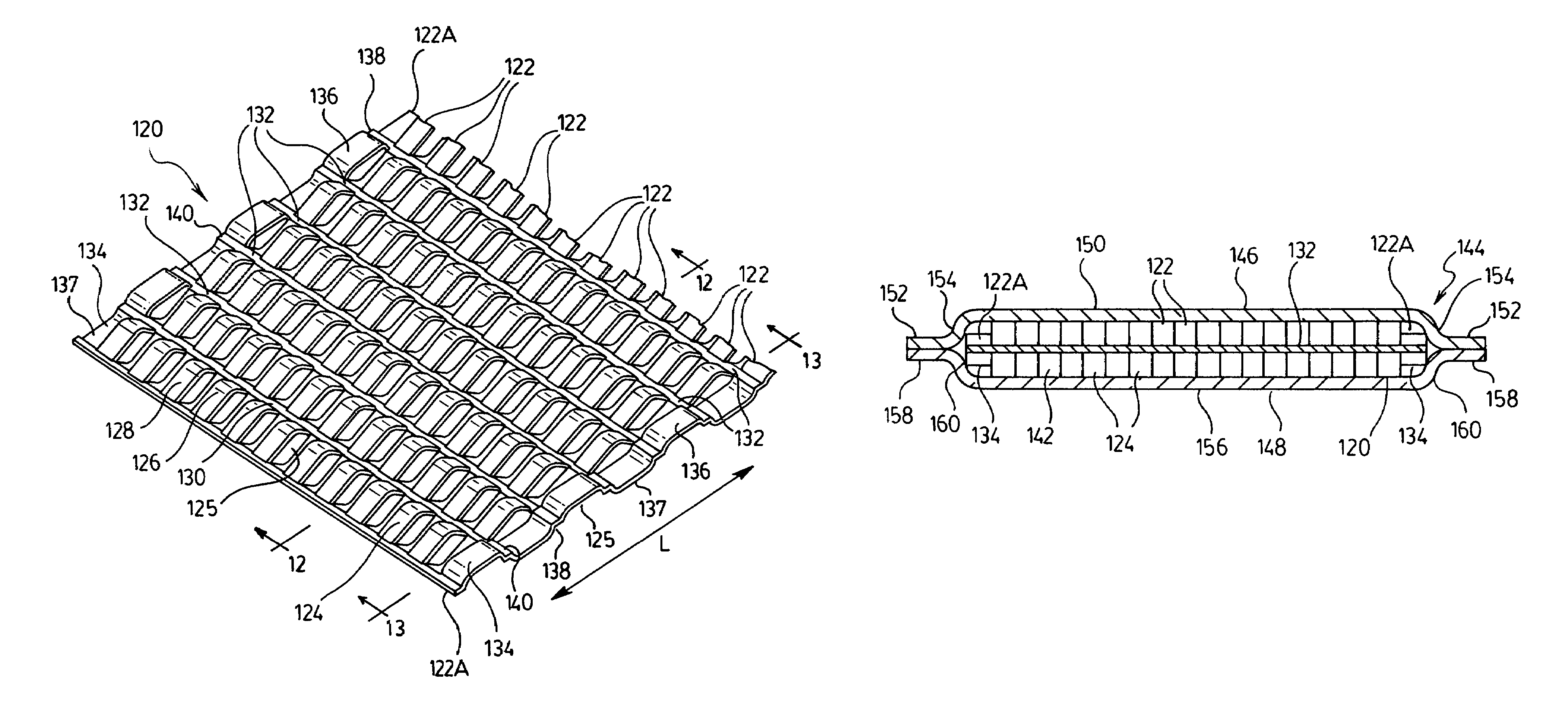
[0029]The following is a description of a number of preferred heat exchangers, plate pairs and turbulizer strips according to the invention. Each heat exchanger described below comprises a pair of plates defining a fluid flow passage. The heat exchangers according to the invention may comprise a single pair of plates, for example as in the oil coolers described by Joshi and Gawve et al. Alternatively, the heat exchangers according to the invention may comprise a plurality of plate pairs extending between a pair of manifolds, such as the type described in the So et al. patent. In the heat exchangers according to the invention, a turbulizer is provided in the fluid flow passage. Unless otherwise stated below, the turbulizers used in the heat exchangers according to the invention may be simple corrugated fins as in the Joshi and Gawve et al. patents or may comprise offset strip fins as described in the So and So et al. patents mentioned above. Preferably, the turbulizers comprise offse...


PUM


Abstract

A heat exchanger comprises at least one tube or plate pair defining a fluid flow passage which is reduced in height across a portion of its width. A turbulizer comprising a plurality of rows of convolutions is received inside the fluid flow passage in either the low pressure drop or high pressure drop orientation. The turbulizer includes convolutions of reduced height in order to at least partially fill the reduced-height portions of the fluid flow passage and thereby reduce bypass flow. In some preferred embodiments of the invention, heat exchanger tubes or plate pairs define fluid flow passages which are reduced in height along their edges, and the turbulizer is similarly reduced in height along its edges.

Description

FIELD OF THE INVENTION[0001]The invention relates to heat exchangers and conductive inserts for use therein, and particularly to plate-type heat exchangers incorporating turbulizers having convolutions of varying height.BACKGROUND OF THE INVENTION[0002]Plate-type heat exchangers comprise at least one pair of spaced-apart plates sealed together at their margins. Each plate pair defines a fluid flow passage having an inlet opening and an outlet opening. In a typical heat exchanger, the edges of the fluid flow passage have a height which is less than the height at the center of the fluid flow passage. The reduction in height adjacent the edges may be due to the manner in which the plates are joined together and / or the edges of the plates may be somewhat rounded as in U.S. Pat. No. 5,636,685 to Gawve et al.[0003]The fluid flow passage may contain a conductive insert to enhance heat transfer and to increase turbulence in the fluid flowing through the flow passage. These conductive insert...

Claims


Application Information

Patent Timeline
Patent Type & Authority Patents(United States)
IPC IPC(8): F28F13/12F28F1/40
CPCF28D1/0316F28F3/025
Inventor CHU, STANLEYCHEONG, ALEX S.ZURAWEL, PETERMACH, PAUL T.
Owner DANA CANADA CORP
Why Eureka
Try Eureka