Modular heat exchanger

a heat exchanger and multi-channel technology, applied in the field of heat exchangers, can solve the problem of limited heat exchangers in the overall siz

Inactive Publication Date: 2011-03-10
CARRIER CORP
View PDF22 Cites 73 Cited by
  • Summary
  • Abstract
  • Description
  • Claims
  • Application Information

AI Technical Summary

Problems solved by technology

As a consequence, the overall size of the heat exchanger is limited by the size of the available brazing furnaces.

Method used


Image

  • Modular heat exchanger
  • Modular heat exchanger
  • Modular heat exchanger

Examples


Embodiment Construction

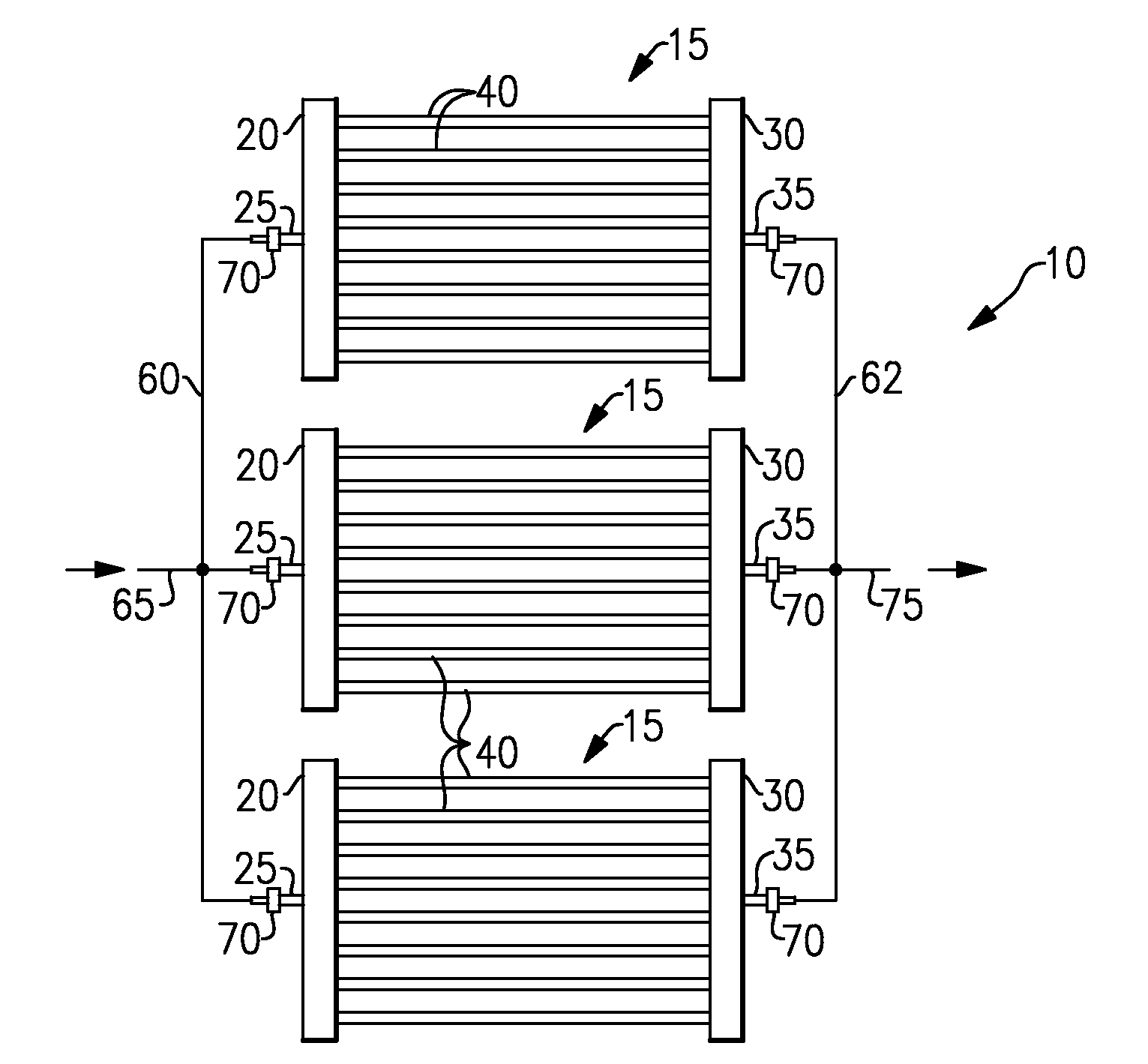
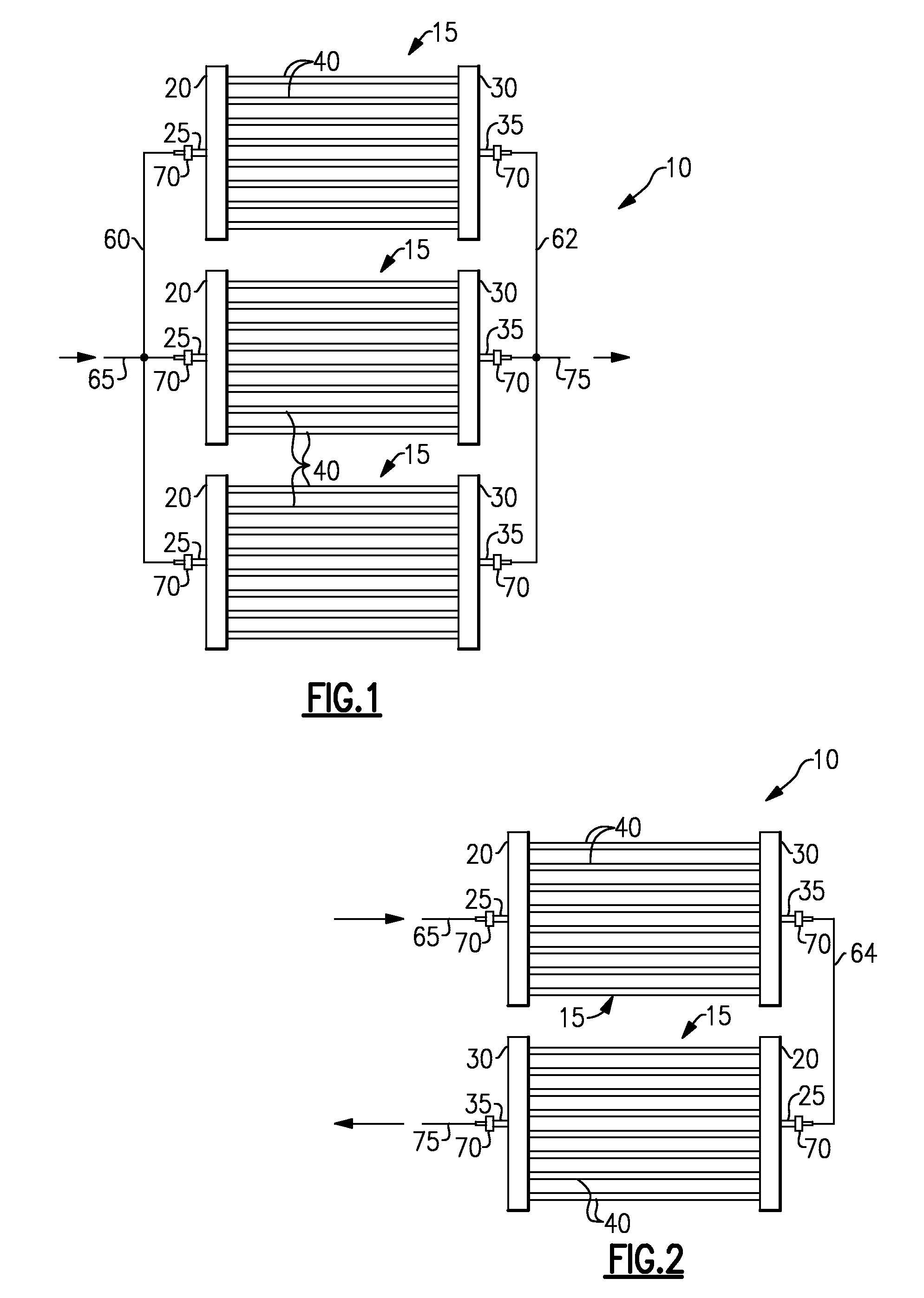
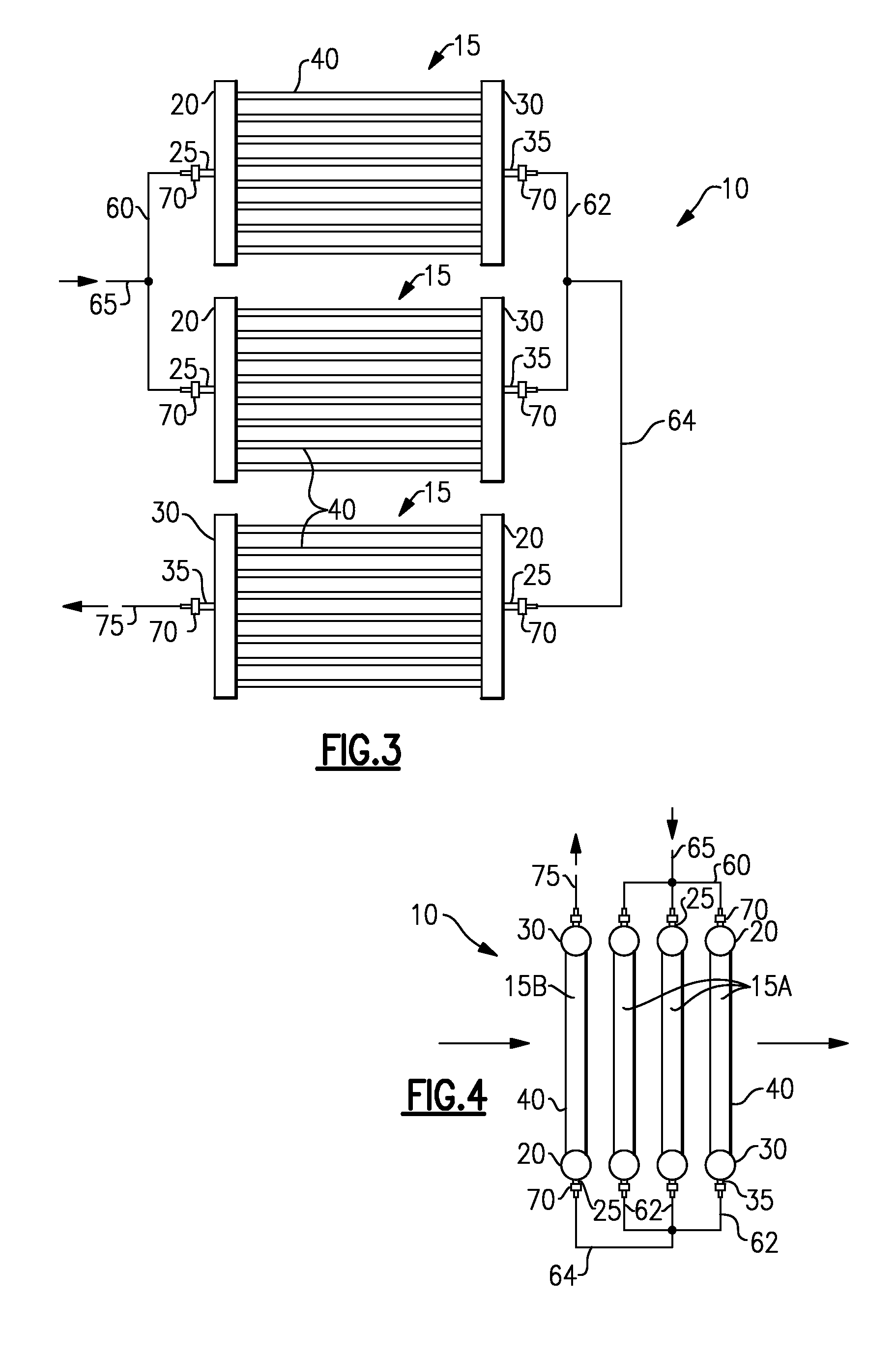
[0023]The modular, multi-channel heat exchanger 10 of the invention will be described in general herein with reference to the various exemplary embodiments depicted in FIGS. 1-8. However, the depicted embodiments are illustrative and are not intended to limit the invention. It is to be understood that the modular, multi-channel tube heat exchanger 10 of the invention may be comprised of any number of a plurality of heat exchanger modules arranged in various configurations.

[0024]In each of the illustrated exemplary embodiments shown in FIGS. 1-4, the heat exchanger 10, in its simplest configuration, includes a plurality, that is two or more, single pass, parallel-tube, multi-channel tube heat exchanger modules 15. In the exemplary embodiment depicted in FIG. 1, the heat exchanger 10 comprises three heat exchanger modules 15 arranged in a parallel configuration, with respect to refrigerant flow. In the exemplary embodiment depicted in FIG. 2, the heat exchanger 10 comprises a pair of ...


PUM


Abstract

A modular multi-channel tube heat exchanger includes a plurality of aluminum heat exchanger modules selectively connected in fluid communication by interconnecting tubing. Each heat exchanger module includes an aluminum inlet header, an aluminum outlet header and a plurality of aluminum heat exchange tubes extending longitudinally therebetween. Each of the plurality of heat exchange tubes may have a plurality of flow paths extending longitudinally in parallel relationship from an inlet end thereof in fluid communication with the inlet header to an outlet end thereof in fluid communication with the outlet header.

Description

FIELD OF THE INVENTION[0001]This invention relates generally to heat exchangers having a plurality of heat transfer tubes extending between a first header and a second header, also sometimes referred to as manifolds, and, more particularly, to modular multi-channel tube heat exchangers.[0002]Refrigerant vapor compression systems are well known in the art. Air conditioners and heat pumps employing refrigerant vapor compression cycles are commonly used for cooling or cooling / heating air supplied to a climate-controlled comfort zone within a residence, office building, hospital, school, restaurant or other facility. Refrigerant vapor compression systems are also commonly used for cooling air or other secondary fluid to provide a refrigerated environment for food items and beverage products within, for instance, display cases in supermarkets, convenience stores, groceries, cafeterias, restaurants and other food service establishments.[0003]Commonly, these refrigerant vapor compression s...

Claims


Application Information

Patent Timeline
Patent Type & Authority Applications(United States)
IPC IPC(8): F28F9/02
CPCF28D1/0478F28D1/05391F28F1/022F28F27/02F28F1/32F28F9/262F28F1/126
Inventor TARAS, MICHAEL F.LIFSON, ALEXANDER
Owner CARRIER CORP
Why Eureka
Try Eureka