
Reheat heat exchanger power generation systems

a technology of power generation system and heat exchanger, which is applied in the direction of indirect heat exchangers, machines/engines, light and heating apparatus, etc., can solve the problems of limiting the maximum attainable efficiency of boilers, affecting the development of such higher temperature turbines, and limiting the maximum temperature of boilers, etc., to enhance the efficiency of power generation systems, low cost, and high thermal efficiency

Inactive Publication Date: 2006-04-04
CLEAN ENERGY SYST
View PDF255 Cites 72 Cited by
  • Summary
  • Abstract
  • Description
  • Claims
  • Application Information

AI Technical Summary

Benefits of technology

[0013]In various different embodiments of this invention additional turbines can be provided, and combustion based reheaters can also be provided to both further expand the working fluid, increase a temperature of the working fluid, and otherwise handle the working fluid in a fashion which maximizes efficiency of the power generation system. Preferably, the fully expanded working fluid is passed to a condenser or other separator where the steam and carbon dioxide within the working fluid are at least partially separated. The carbon dioxide can then be sequestered from the atmosphere, if desired, such as by pressurization and injection into a subterranean formation, such as an at least partially depleted oil well, natural gas field, or a sequestration site such as a deep saline aquifer or other subterranean formation.
[0017]Another object of the present invention is to provide zero emissions power generation systems which can use existing commonly available steam turbine technology while still attaining high thermal efficiencies.
[0018]Another object of the present invention is to provide non-polluting combustion based power generation systems utilizing existing technology for relatively low cost new power plant installation and for retrofitting existing power plants.
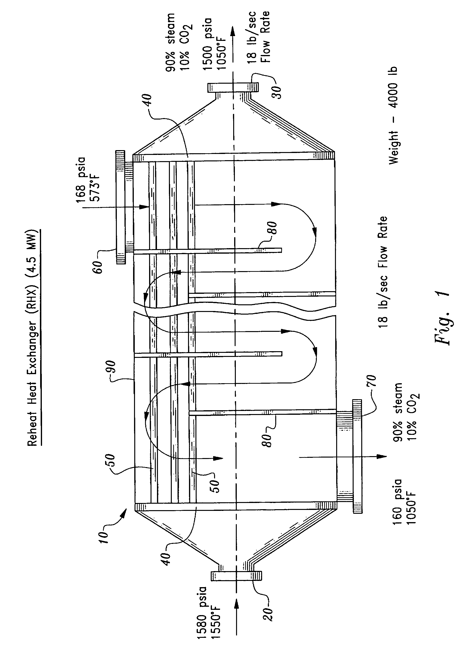
[0019]Another object of the present invention is to provide a reheat heat exchanger which can transfer heat from a high pressure path to a low pressure path of the same working fluid on either side of an expander within a power generation system to enhance an efficiency of the power generation system.

Problems solved by technology

However, the constraints of different materials available for use within the boiler and within the turbine restrict the practical temperatures which can be achieved at the inlets to the turbine, hence limiting maximum attainable efficiency.
While high temperatures (above 1050° F.) do present some challenges in turbine design and operation, boiler maximum temperature limitations have been the primary impediment to increasing inlet temperatures for turbines within steam power plants.
(for example) might be relatively easily designed and manufactured, the relative difficulty in providing boilers that can provide steam at temperatures above 1050° F. have made the development of such higher temperature turbines unimportant.
This dilution of the working fluid and reduction in temperature decreases the overall efficiency of the power generation system.

Method used


Image

  • Reheat heat exchanger power generation systems
  • Reheat heat exchanger power generation systems
  • Reheat heat exchanger power generation systems

Examples


Embodiment Construction

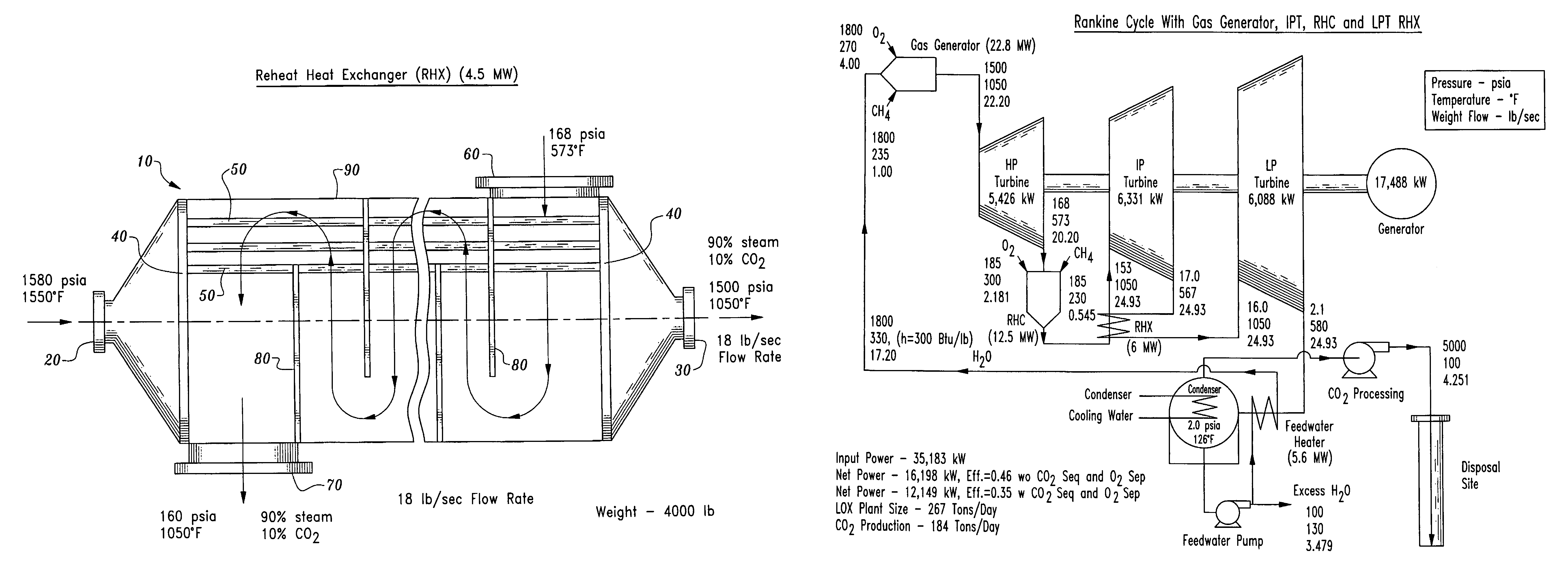
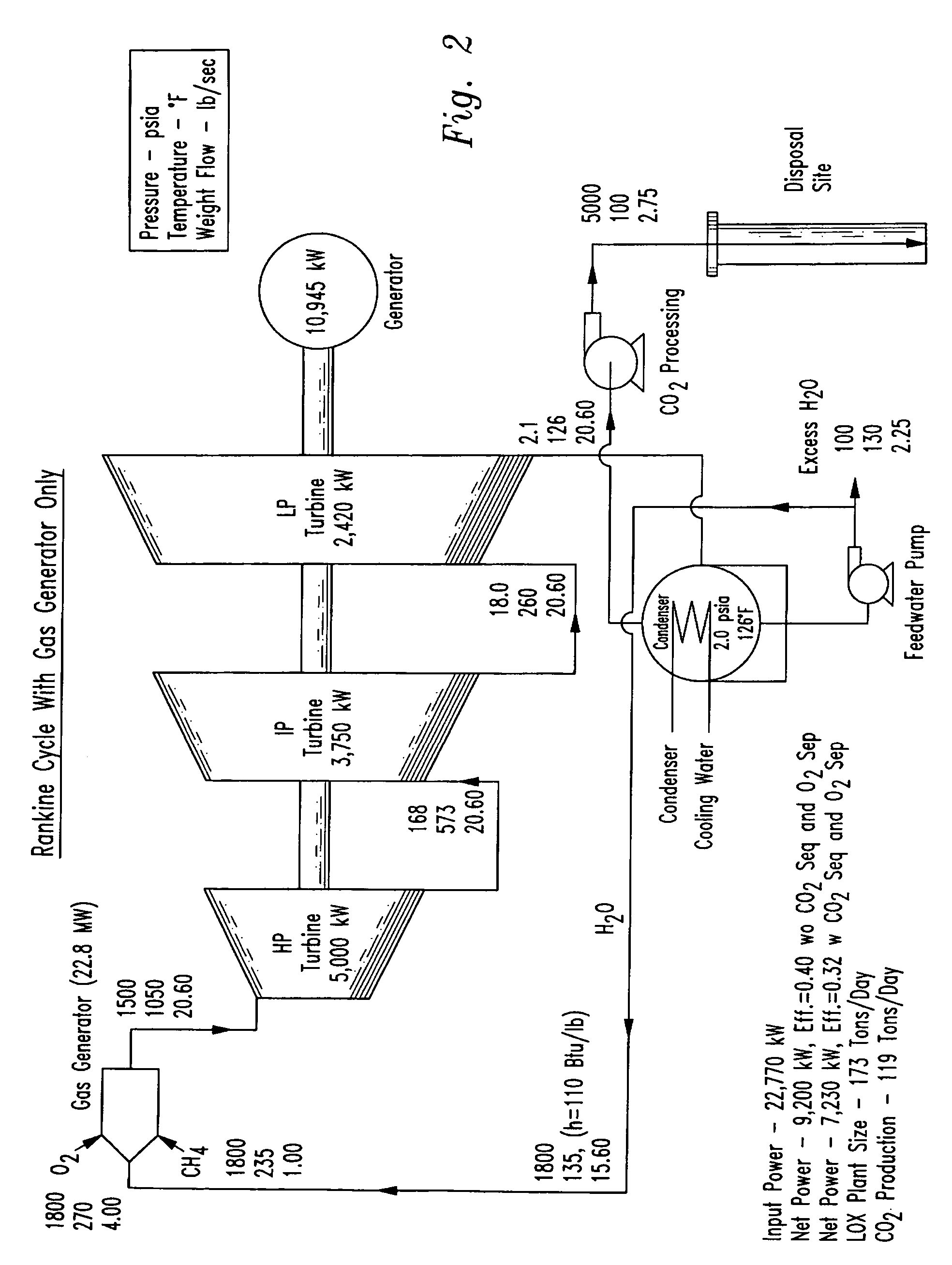
[0028]Referring to the drawings, wherein like reference numerals represent like parts throughout the various drawing figures, reference numeral 10 (FIG. 1) is directed to a reheat heat exchanger for use within a combustion based power generation system, such as those depicted in FIGS. 2–6 for enhancement of thermal efficiency of such power generation systems. The reheat heat exchanger 10 is particularly suited for both decreasing a temperature of a working fluid before entering a high pressure turbine and for increasing a temperature of the working fluid after it has discharged from the high pressure turbine and before being passed on to a lower pressure turbine. In this way, a single gas generator producing the working fluid at a temperature higher than maximum inlet temperatures for the turbines can be effectively utilized to achieve the maximum temperature for the inlets of both the high temperature turbine and a lower pressure turbine, without requiring, for instance, a combusti...


PUM


Abstract

A reheat heat exchanger is provided particularly for use in Rankine cycle power generation systems. The reheat heat exchanger includes a high pressure path between a high pressure inlet and a high pressure outlet. The reheat heat exchanger also includes a low pressure path between a low pressure inlet and a low pressure outlet. The two paths are in heat transfer relationship. In a typical power generation system utilizing the reheat heat exchanger, the high pressure inlet is located downstream from a source of high temperature high pressure working fluid. An expander is located downstream from the high pressure outlet and upstream from the low pressure inlet. A second expander is typically provided downstream from the low pressure outlet. The reheat heat exchanger beneficially enhances the efficiency of power generation systems, particularly those which utilize expanders having inlet temperatures limited to below that produced by the source of working fluid.

Description

CROSS-REFERENCE TO RELATED APPLICATIONS[0001]This application claims benefit under Title 35, United States Code §119(e) of U.S. Provisional Application No. 60 / 453,760 filed on Mar. 10, 2003.FIELD OF THE INVENTION[0002]The following invention relates to power generation systems such as Rankine cycle steam power generation systems which include boilers or other sources of high temperature, high pressure working fluid, turbines or other expanders to output power from the system, and optionally other equipment. More particularly, this invention relates to such power generation systems which beneficially maximize efficiency by providing a reheat heat exchanger having a high pressure path upstream from a first expander and a low pressure path downstream from the first expander.BACKGROUND OF THE INVENTION[0003]Rankine cycle power generation systems, such as steam power plants, have long been in use as a source of electric power. A typical steam power plant includes a boiler which heats a p...

Claims


Application Information

Patent Timeline
IPC IPC(8): F02C3/10F01K25/00F28D7/16
CPCF01K25/005F28D7/1607Y02E20/16Y02E20/32Y02E20/34
Inventor VITERI, FERMIN
Owner CLEAN ENERGY SYST
Learn More