Energy Conversion Using Rankine Cycle System

a technology of energy conversion and rankine cycle, applied in the field of energy conservation, can solve the problems of large-scale steam turbines with low power generation efficiency and confuse the efficiency of the combined heat and power system operation

Inactive Publication Date: 2012-03-01
UOP LLC
View PDF9 Cites 74 Cited by
  • Summary
  • Abstract
  • Description
  • Claims
  • Application Information

AI Technical Summary

Benefits of technology

[0006]A broad embodiment of the invention is apparatus for generating power from two or more process streams having different temperatures in an organic Rankine cycle system, comprising one or more lower-temperature exchangers for exchanging heat between at least one lower-temperature process stream and a liquid Rankine-cycle working fluid to obtain a heated working fluid; one or more higher-temperature exchangers for exchanging heat between at least one higher-temperature process stream and the heated working fluid to obtain a vaporized working fluid; an expander driven by the vaporized working fluid to produce power to an output shaft and a reduced-pressure working fluid; a working-fluid condenser for reducing the temperature of the reduced-pressure working fluid to obtain a liquid working fluid; a pump to circulate the liquid working fluid in the cycle system; conduits connecting the one or more lower-temperature exchangers, higher-temperature exchangers, expander, condenser, pump, and working-stream bypasses around one or both of the exchangers; and, a controller for monitoring flow rates, temperatures and pressures of the two or more process streams and working fluid and for providing control signals to the pump and expander.
[0007]A more specific embodiment is an apparatus for generating power from two or more process streams having different temperatures in an organic Rankine cycle system, comprising: a lower-temperature condenser for condensing at least one lower-temperature process stream by heating a liquid Rankine-cycle working fluid to obtain a heated working fluid; a higher-temperature condenser for condensing at least one higher-temperature process stream by heating the heated working fluid to obtain a vaporized working fluid; an expander driven by the vaporized working fluid to produce power to an output shaft and a reduced-pressure working fluid; a working-fluid condenser for reducing the temperature of the reduced-pressure working fluid to obtain a liquid working fluid; a pump to circulate the liquid working fluid in the cycle system; conduits connecting the lower-temperature condenser, higher-temperature condenser, expander, condenser, pump, and working-stream bypasses around one or both of the condenser; and, a controller for monitoring flow rates, temperatures and pressures of the two or more process streams and working fluid and for providing control signals to the pump and expander.
[0008]An alternative embodiment is a process for generating power from two process streams having different temperatures in an organic Rankine cycle system, comprising cooling a lower-temperature process stream by heating a liquid Rankine-cycle working fluid to obtain a heated working fluid; cooling a higher-temperature process stream by heating the heated working fluid to obtain a vaporized working fluid; expanding the vaporized working fluid to produce power to an output shaft and a reduced-pressure working fluid; and, condensing the reduced-pressure working fluid to obtain the liquid Rankine-cycle working fluid.

Problems solved by technology

Thus, a steam Rankine cycle using low-pressure steam as the working fluid results in a large-sized steam turbine with low power-generation efficiency.
These systems are particularly appropriate when the potential thermal output is variable and direct load matching becomes difficult, confounding efficient operation of the combined heat and power system.

Method used


Image

  • Energy Conversion Using Rankine Cycle System
  • Energy Conversion Using Rankine Cycle System
  • Energy Conversion Using Rankine Cycle System

Examples


example

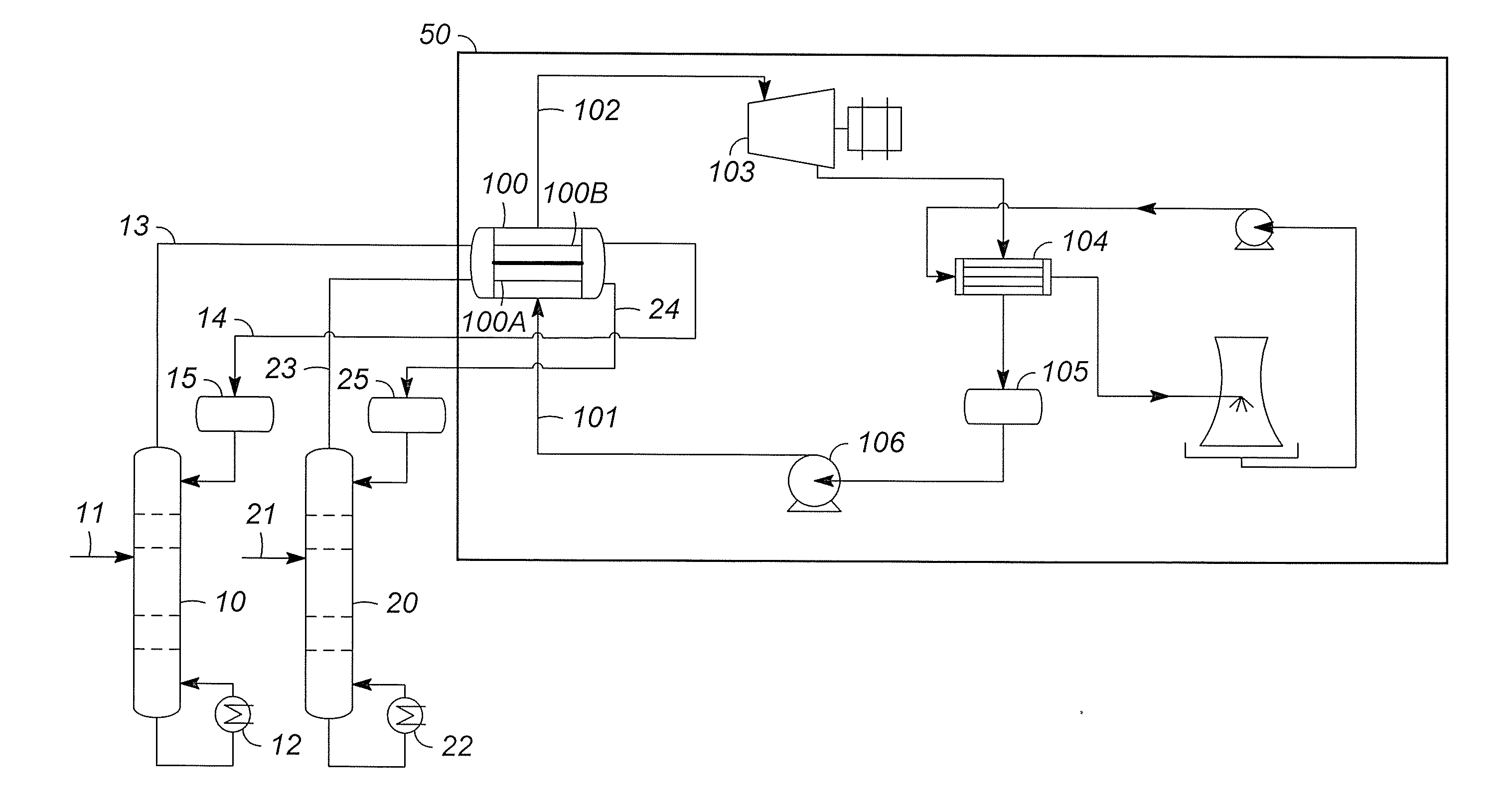
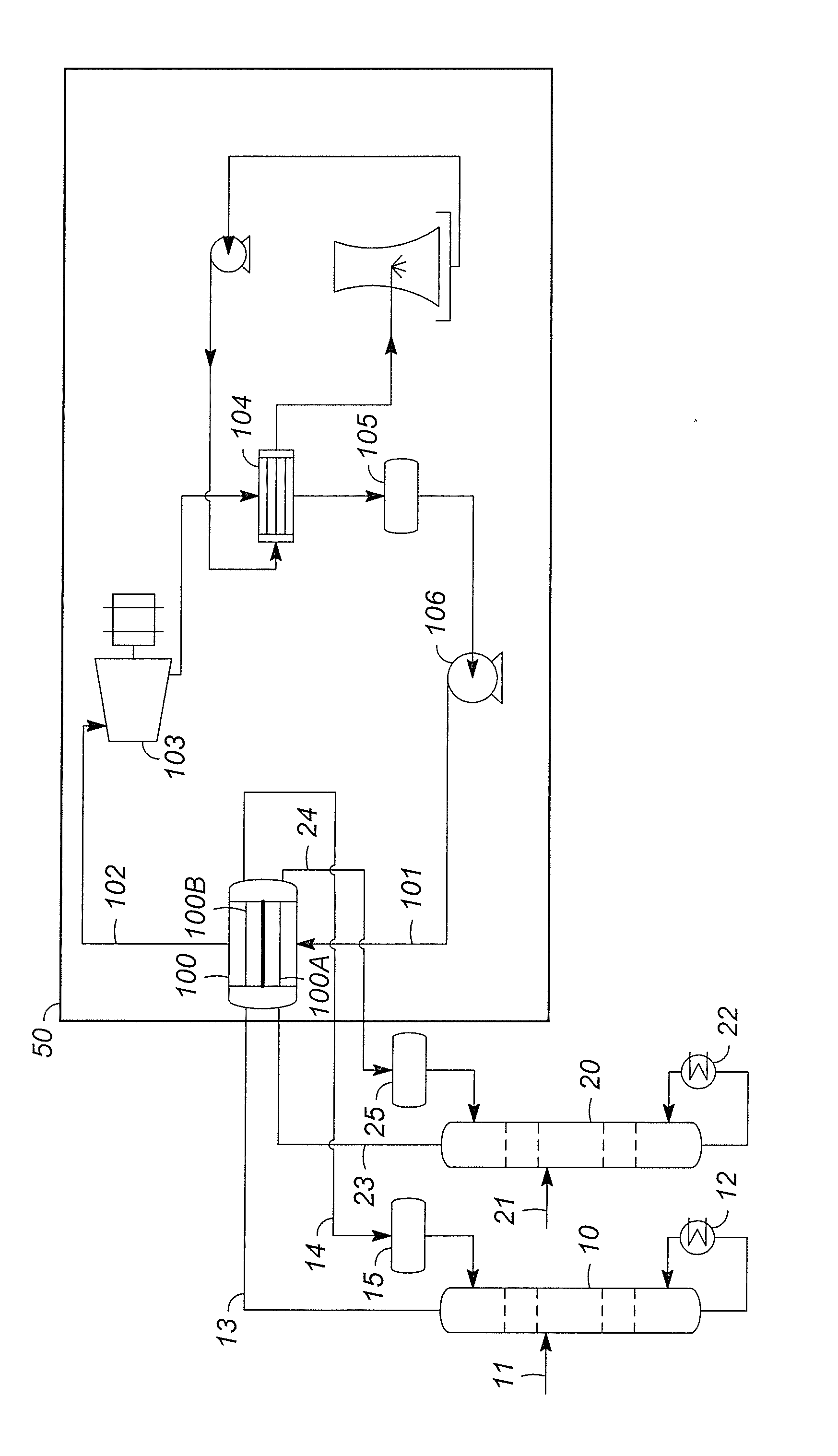
[0023]The following example illustrates the benefits of the invention using ORC in an aromatics complex producing 900,000 tons / year of para-xylene. Aspects of the aromatics complex are described in U.S. Pat. No. 6,740,788 which is incorporated herein by reference. Columns 10 and 20 as described in the FIGURE of the present application are, respectively, distillation columns in an adsorption separation unit separating C8-aromatics raffinate from desorbent and para-xylene-rich extract from desorbent. The raffinate column is, relatively, the high-temperature column and the extract column is the low-temperature column. To compare ORC to air cooling and water cooling, the heat duties are as follows:

Heat Rejected(MW)T-in (° C.)T-out (° C.)Extract Column Overhead34.0151.1128.9Raffinate Column Overhead90.6152.6140.8Total124.6——

[0024]The net power benefit of using ORC relative to air and water condenser cases is calculated using the following equations:

[0025]For Water Cooling:

[0026]Net Power...


PUM


Abstract

A process for recovering waste heat in an organic Rankine cycle system which comprises passing a liquid phase working fluid through heat exchange in successive communication with two or more process streams which thus heat the working fluid, removing a vapor phase working fluid from the heat exchanger, passing the vapor phase working fluid to an expander wherein the waste heat is converted into mechanical energy, and passing the vapor phase working fluid from the expander to a condenser wherein the vapor phase working fluid is condensed into the liquid phase working fluid.

Description

BACKGROUND OF THE INVENTION[0001]1. Field of the Invention[0002]The present invention generally relates to energy conservation in the cooling or condensing of process streams. Waste heat from process streams may be converted in organic Rankine cycle systems into mechanical energy to generate electric power.[0003]2. Discussion of the Background Art[0004]Rankine cycle systems are known to be a simple and reliable means to convert heat energy into mechanical shaft power. Organic working fluids are useful in place of water / steam when low-grade thermal energy is encountered. Water / steam systems operating with low-grade thermal energy (typically 275° C. and lower) will have associated high volumes and low pressures. Thus, a steam Rankine cycle using low-pressure steam as the working fluid results in a large-sized steam turbine with low power-generation efficiency. To keep system size small and efficiency high, organic working fluids with boiling points near room temperature are employed. ...

Claims


Application Information

Patent Timeline
Patent Type & Authority Applications(United States)
IPC IPC(8): F01K25/06F01K23/06
CPCF01K25/10F01K23/064Y02P80/15
Inventor ULAS ACIKGOZ, SAADETZHU, XIN X.DALY, PHILLIP F.
Owner UOP LLC
Why Eureka
Try Eureka