Cold-storage heat exchanger

a heat exchanger and cold storage technology, applied in the field of cold storage heat exchangers, can solve the problems of increasing costs and frost breakag

Active Publication Date: 2010-12-09
DENSO CORP
View PDF22 Cites 72 Cited by
  • Summary
  • Abstract
  • Description
  • Claims
  • Application Information

AI Technical Summary

Benefits of technology

[0009]The present invention is made in view of the above matters, and it is an object of the invention to provide a cold storage heat exchanger, which can perform by using a single heat exchanger, a cold storage, a cooling of a compartment due to a refrigerant tube, and a cooling of the compartment due to a cold release of a cold storage material, thereby preventing a problem regarding a freezing break.
[0013]Furthermore, the cold-storage side air passage formed by the plural protrusions or the plural recess portions is provided with the space through which condensed water generated in the cold storage time of the cold storage material is drained to an outer side along the cold-storage side air passage. Therefore, it can prevent a frost break such as a break of the refrigerant tube and the cold storage container from being caused, when condensed water is frozen and the volume of the frozen part is expanded.
[0016]Furthermore, the cold-storage side air passage formed by the plural protrusions or the plural recess portions is provided with the space through which condensed water generated in the cold storage time of the cold storage material is drained to an outer side along the cold-storage side air passage. Therefore, it can prevent a frost break such as a break of the refrigerant tube and the cold storage container from being caused, when condensed water is frozen and the volume of the frozen part is expanded.
[0018]The cold storage container is provided with the inner fin, and a ratio of the contact area is set in a range of 10% to 50% when the cold storage container partially contacts the outer surface of the refrigerant tube due to the protrusion portions and the recess portions. Therefore, it can restrict a heat exchange performance from being reduced in the cold storage heat exchanger. For example, in this case, it is also possible to make the performance reduce to be less than 1%. If the ratio of the contact area is smaller than 10%, the bonding ratio is insufficient, thereby reducing heat exchange performance. In contrast, if the ratio of the contact area is larger than 50%, heat exchange performance of the inner fin is reduced. Specifically, when the bonding ratio or a necessary brazing ratio is made larger than 50% so as to make the bonding or the brazing in preferential, the bonding ratio or the brazing ratio between the inner fin and the cold storage container is reduced, and thereby heat exchange performance of the entire cold storage heat exchanger is reduced.
[0020]Because the cold-storage side air passage is formed to have the slanting portions, the generated condensed water can be promptly discharged outside along the slanting portions. Therefore, it can prevent the refrigerant tube and the cold storage container from being broken due to the volume expansion of the frozen condensed water, thereby preventing a freezing crack. Thus, even when the condensed water remains on the surface of the cold storage heat exchanger and is frozen thereon, the frozen ice can be easily removed, thereby further preventing the freezing crack. Because condensed water can flow the slanting portions to be separated into the left and right sides, the length of the slanting portions can be made shorter, thereby improving the discharge performance of the condensed water.

Problems solved by technology

Thus, in order to perform the cooling of a vehicle compartment, another evaporator used as a cooling heat exchanger is required, thereby increasing the cost.
Furthermore, when the refrigerant tube and the cold storage container are bonded and brazed, a clearance may be caused between a surface of the cold storage container and a surface of the refrigerant tube, and thereby condensed water generated on the evaporator surface may enter into the clearance.
When the condensed water is frozen in the clearance, the volume of the frozen part is expanded, thereby causing a frost break such as a break of the refrigerant tube and the cold storage container.

Method used


Image

  • Cold-storage heat exchanger
  • Cold-storage heat exchanger
  • Cold-storage heat exchanger

Examples


first embodiment

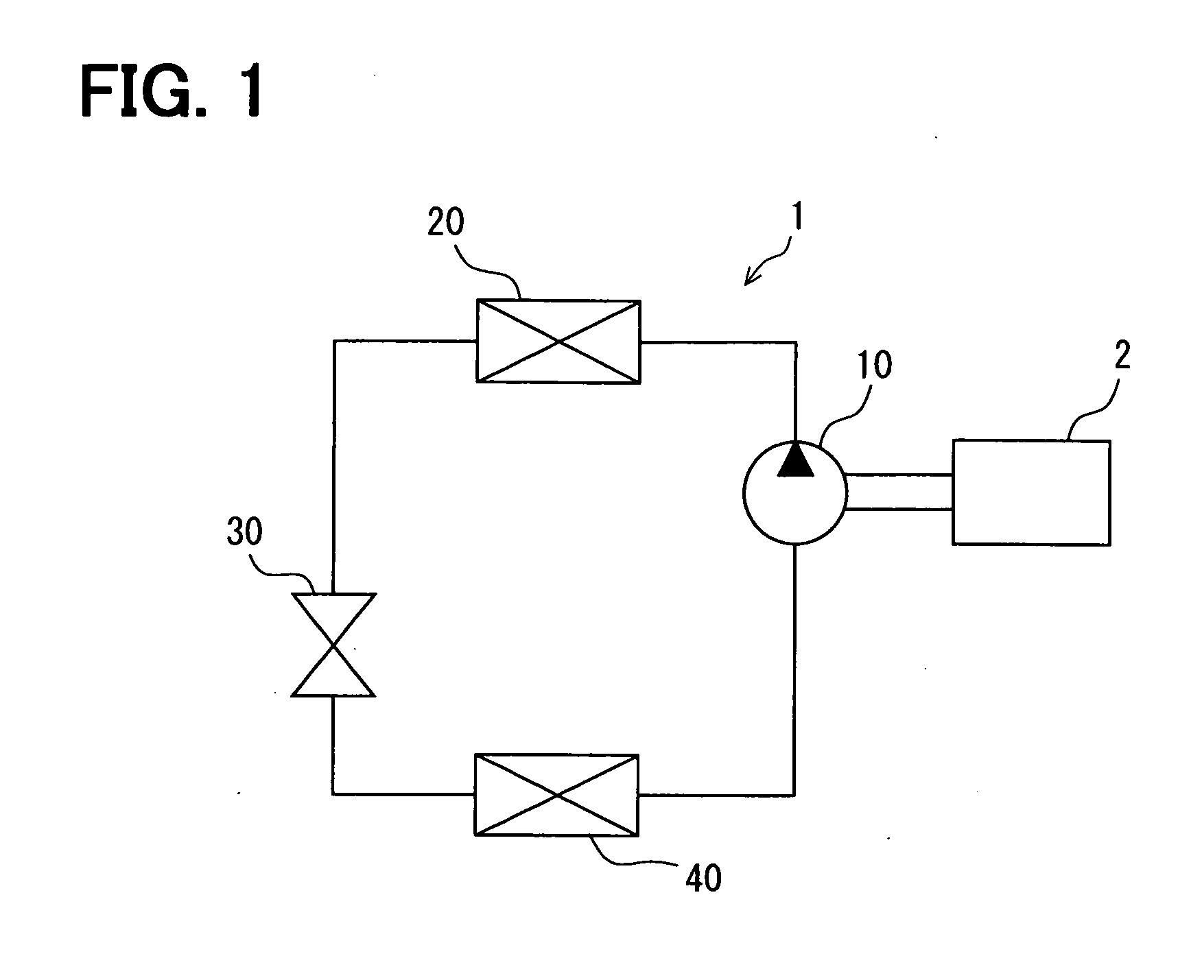
[0054]FIG. 1 is a schematic diagram showing a refrigerant cycle device 1 for a vehicle air conditioner, according to a first embodiment of the invention. The refrigerant cycle device 1 for an air conditioner includes a compressor 10, a radiator 20, a decompression device 30 and an evaporator 40. The components of the refrigerant cycle device 1 are connected in cycle by piping, thereby configuring a refrigerant circuit.

[0055]The compressor 10 is driven by an internal combustion engine (or electrical motor etc.) that is a driving source 2 for a vehicle traveling. Thus, the compressor 10 is also stopped when the driving source 2 stops. The compressor 10 draws refrigerant flowing out of the evaporator 40, compresses the drawn refrigerant, and discharge the compressed refrigerant toward the radiator 20. The radiator 20 is configured to cool high-temperature refrigerant from the compressor 10. The radiator 20 is also called as a condenser. The decompression device 30 decompresses the refr...

second embodiment

[0096]Next, a second embodiment of the invention will be described. FIG. 9 is a side view showing a cold storage container 47 according to the second embodiment, corresponding to that of FIG. 6. In the present embodiment and the following embodiments, a part that corresponds to a matter described in the above first embodiment may be assigned with the same reference numeral, and the explanation for the part may be omitted. Only different structures and features different from the above-described first embodiment will be mainly described in the present embodiment and the following embodiments.

[0097]As shown in FIG. 9, in the second embodiment, the cold storage container 47 is provided with plural protrusion portions 47a1 each having an open-hole shape at its center portion (i.e., protrusion tip surface). As shown in FIG. 10, via open-hole portions 47a3 opened at the protrusion portions 47a1, the cold storage material 50 in the cold storage container 47 can directly contact the surface...

third embodiment

[0109]FIG. 17 is an enlarged sectional view showing relationships between a refrigerant tube, a cold storage container and an air-side fin, according to a third embodiment, in a section taken along the line V-V of FIG. 3 similarly to FIG. 5. In the third embodiment, a bonding ratio of the outer surface of the cold storage container 47 or a bonding ratio of the inner surface of the cold storage container 47 is set in a predetermined range.

[0110]In FIG. 17, 460 indicates a cooling air passage, and 461a indicates a cold-storage side air passage. In a case where the surface of the cold storage container 47 is configured to have ribs of an uneven shape, when an area ratio of the outer surface of the cold storage container 47 defining the protrusion portions 47a1 is set at X %, and when an area ratio of the inner surface of the cold storage container 47 defining the recess portion 47a2 is set at Y %, X+Y=100%. Here, the outer surface of the cold storage container 47 defining the protrusio...


PUM


Abstract

An outer surface of a cold-storage container (or a refrigerant tube) is provided with a plurality of protrusion portions or recess portions. A cooling air passage, in which air flows to cool a space to be cooled in a cold storage time and in a cold release time of the cold storage material, is provided to contact a surface of the refrigerant tube on a side opposite to the cold storage container bonded to the refrigerant tube. The refrigerant tubes and the cold storage container form therebetween a cold-storage side air passage by the protrusion portions or the recess portions, such that air flows in the cold-storage side air passage separated from the cooling air passage. For example, the cold-storage side air passage is provided with a slanting space that causes condensed water or ice generated in the cold storage time to be drained along the cold-storage side air passage.

Description

CROSS REFERENCE TO RELATED APPLICATION[0001]This application is based on Japanese Patent Applications No. 2009-136630 filed on Jun. 5, 2009, and No. 2010-095227 filed on Apr. 16, 2010, the contents of which are incorporated herein by reference in its entirety.FIELD OF THE INVENTION[0002]The present invention relates to a cold-storage heat exchanger used for a refrigerant cycle device.BACKGROUND OF THE INVENTION[0003]Conventionally, a cold-storage type cooling device for a trucker nap, described in JP 8-175167A, is known. A container, in which a cold-storage material is sealed, is made of a resin film, in the cold-storage type cooling device of JP 8-175167A. A recess portion and a protrusion portion are provided on a surface of the container, and are configured such that an air passage for air cooled by the cold-storage material is formed by the recess portion.[0004]In a cold storage time, refrigerant flows into refrigerant tubes in which the container is inserted, so as to configure...

Claims


Application Information

Patent Timeline
Patent Type & Authority Applications(United States)
IPC IPC(8): F25D21/14F25D17/02F25D17/04F28F7/00
CPCF25B39/02F28D1/0333F28D1/05391F28D20/02F28D2020/0013F28D2021/0085F28F9/00Y02E60/145F28F3/046F28F17/005F28D15/00F28F1/10F28F3/025Y02E60/14F25D13/02F25D17/005F25D19/00
Inventor YAMADA, ATSUSHIINOUE, SEIJIMIYATA, YOSHIOYOKOYAMA, NAOKIHASEGAWA, ETSUOABEI, JUNISHIKAWA, HIROSHIOTA, AUNHAGIHARA, KOUTA
Owner DENSO CORP
Why Eureka
Try Eureka