Pumping system with power optimization

a pumping system and power optimization technology, applied in the direction of machines/engines, mechanical equipment, positive displacement liquid engines, etc., can solve the problems of pumping at a rate that provides insufficient flow and/or pressure, installation of unsuitably sized pumps, and inability to easily change the speed settings

Active Publication Date: 2010-03-30
DANFOSS POWER ELECTRONICS AS +1
View PDF122 Cites 80 Cited by
  • Summary
  • Abstract
  • Description
  • Claims
  • Application Information

AI Technical Summary

Problems solved by technology

Once the pump is installed, the speed settings typically are not readily changed to accommodate changes in the pool conditions and / or pumping demands.
These assumptions can introduce a degree of error to the calculations that could result in the installation of an unsuitably sized pump.
However, adjusting the pump to one of the settings may cause the pump to operate at a rate that exceeds a needed rate, while adjusting the pump to another setting may cause the pump to operate at a rate that provides an insufficient amount of flow and / or pressure.
In such a case, the pump will either operate inefficiently or operate at a level below that which is desired.

Method used


Image

  • Pumping system with power optimization
  • Pumping system with power optimization
  • Pumping system with power optimization

Examples


Embodiment Construction

[0023]Certain terminology is used herein for convenience only and is not to be taken as a limitation on the present invention. Further, in the drawings, the same reference numerals are employed for designating the same elements throughout the figures, and in order to clearly and concisely illustrate the present invention, certain features may be shown in somewhat schematic form.

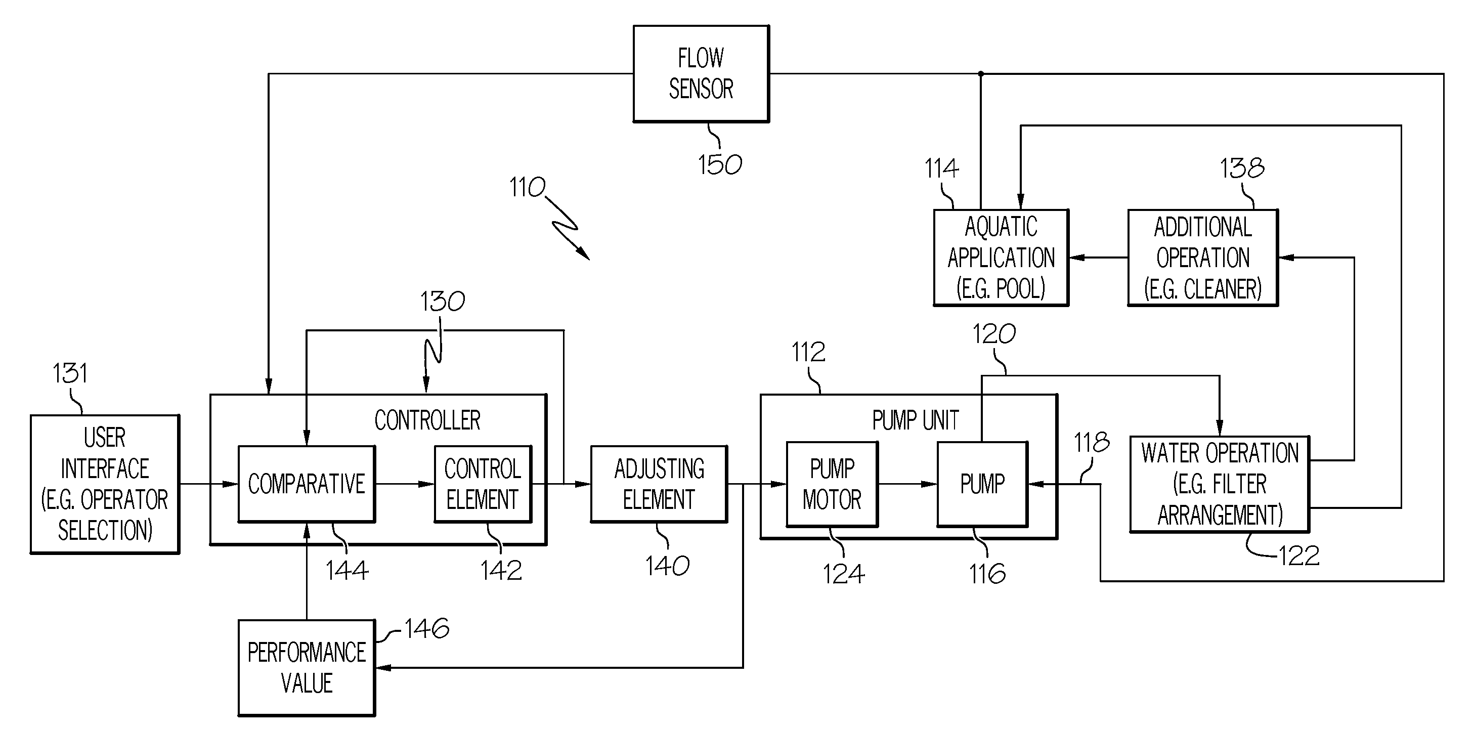
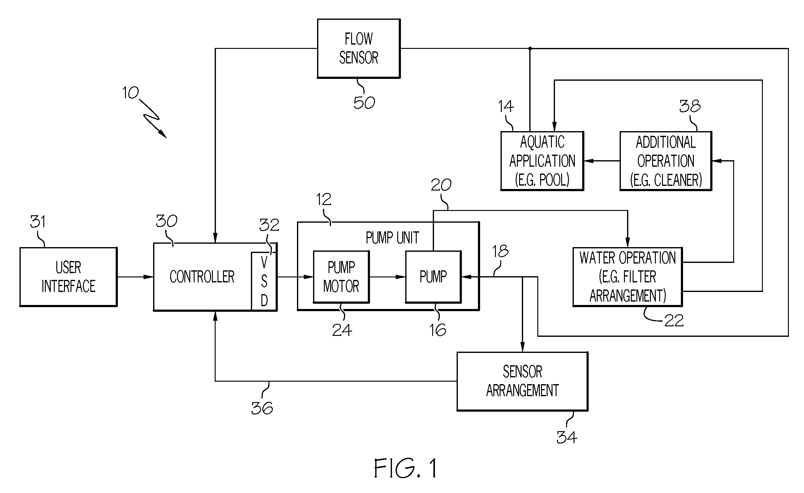
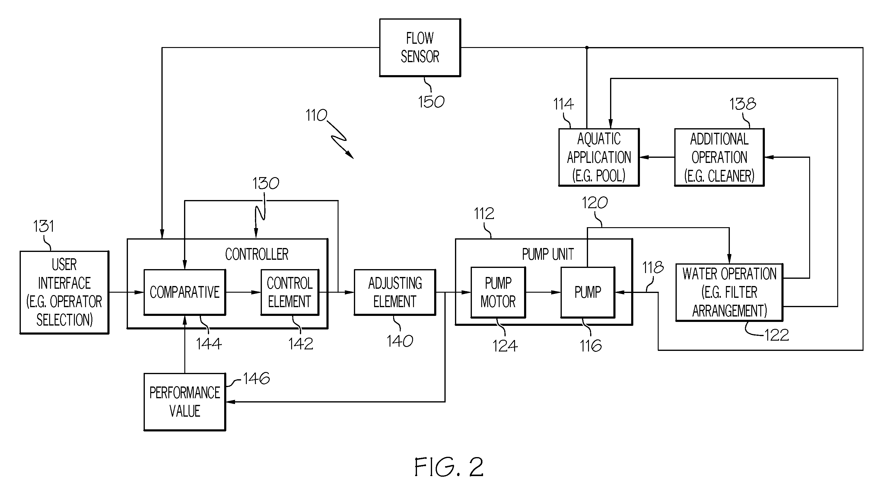
[0024]An example variable-speed pumping system 10 in accordance with one aspect of the present invention is schematically shown in FIG. 1. The pumping system 10 includes a pump unit 12 that is shown as being used with a pool 14. It is to be appreciated that the pump unit 12 includes a pump 16 for moving water through inlet and outlet lines 18 and 20.

[0025]The swimming pool 14 is one example of a pool. The definition of “swimming pool” includes, but is not limited to, swimming pools, spas, and whirlpool baths. Features and accessories may be associated therewith, such as water jets, waterfalls, fountains, pool...


PUM


Abstract

The present invention provides a pumping system for moving water of a swimming pool, including a water pump and a variable speed motor. In one example, a target volume amount of water and an operational time period is provided, and the operational time period is altered based upon a volume of water moved. In another example, operation of the motor is altered based upon the volume of water moved. In addition or alternatively, a target flow rate of water to be moved by the water pump is determined based upon the target volume amount and a time period. In addition or alternatively, a plurality of operations are performed on the water, and a total volume of water moved by the pump is determined. In addition or alternatively, an optimized flow rate value is determined based upon power consumption.

Description

RELATED APPLICATIONS[0001]This application is a continuation-in-part application of U.S. application Ser. No. 10 / 926,513, filed Aug. 26, 2004, and U.S. application Ser. No. 11 / 286,888, filed Nov. 23, 2005, the entire disclosures of which are hereby incorporated herein by reference.FIELD OF THE INVENTION[0002]The present invention relates generally to control of a pump, and more particularly to control of a variable speed pumping system for a pool.BACKGROUND OF THE INVENTION[0003]Conventionally, a pump to be used in a pool is operable at a finite number of predetermined speed settings (e.g., typically high and low settings). Typically these speed settings correspond to the range of pumping demands of the pool at the time of installation. Factors such as the volumetric flow rate of water to be pumped, the total head pressure required to adequately pump the volume of water, and other operational parameters determine the size of the pump and the proper speed settings for pump operation....

Claims


Application Information

Patent Timeline
Patent Type & Authority Patents(United States)
IPC IPC(8): F04B49/06
CPCF04B49/20F04D1/00F04D15/0066F04D13/06E04H4/1245F04B49/06F04B49/065F04D27/004
Inventor STILES, JR., ROBERT W.BERTHELSEN, LARS HOFFMANNROBOL, RONALD B.YAHNKER, CHRISTOPHER R.RUNARSSON, EINAR KJARTAN
Owner DANFOSS POWER ELECTRONICS AS
Why Eureka
Try Eureka