Supercharge Your Innovation With Domain-Expert AI Agents!

Hot cold water supply crossover manifold

a technology for hot water supply and manifolds, applied in the field of manifold assembly, can solve the problems of increasing the overall chance of manifold leakage, every joint that is made has a chance of failing and leaking, and the cost of parts and labor is high

Inactive Publication Date: 2010-04-06
GRAYBEAL MICHAEL
View PDF3 Cites 1 Cited by
  • Summary
  • Abstract
  • Description
  • Claims
  • Application Information

AI Technical Summary

Benefits of technology

"The invention is a crossover manifold system for hot and cold water faucet pairs that are arranged back to back on opposite sides of a partition. The system includes two pairs of manifold tubes that cross over each other. The manifold tubes have a central section, first and second intermediate sections, and first and second distal sections. The first and second distal sections are parallel to each other and to the central section. The system can be installed by attaching the manifold tubes to a mounting bracket and connecting them to hot and cold water supply lines and valves on opposite sides of the partition. The technical effect of the invention is to provide a convenient and efficient way to install hot and cold water faucet pairs in a partitioned space."

Problems solved by technology

While being expedient, this assembly of parts is costly in terms of parts and especially labor and thus is undesirable.
In addition, every joint that is made has a chance of failing and leaking, and therefore the numerous joints required for producing a hand-made crossover manifold increases the overall chances that the manifold will leak.
Finally, such a do-it-yourself solution does not provide a convenient mechanism for holding the manifold in place during installation.
However, such a manifold is very expensive such that the purchase price approaches the cost of a plumber's time to assemble a self-made manifold from individual components.
Furthermore, such devices are extremely heavy, typically having two ends cast from brass, making installation difficult.
Among the difficulties associated with installation is the fact that the heavy brass end fittings require application of a considerable amount of heat to solder copper pipes onto them.
In use, the heavy brass fittings also absorb a great deal of heat when running hot water through them and thus require running hot water longer to produce acceptably hot water at the basin.
In addition, installation of this prior art device requires the hot and cold water supply lines to be on opposite ends of the manifold and is not easily adapted to situations where the hot and cold water supply lines are on the same side of the manifold.
Finally, these prior art manifold systems are not readily compatible with newer push- or press-to-fit connectors, further reducing their versatility.

Method used


Image

  • Hot cold water supply crossover manifold
  • Hot cold water supply crossover manifold
  • Hot cold water supply crossover manifold

Examples


Embodiment Construction

[0034]The following description of the preferred embodiment(s) is merely exemplary in nature and is in no way intended to limit the invention, its application, or uses.

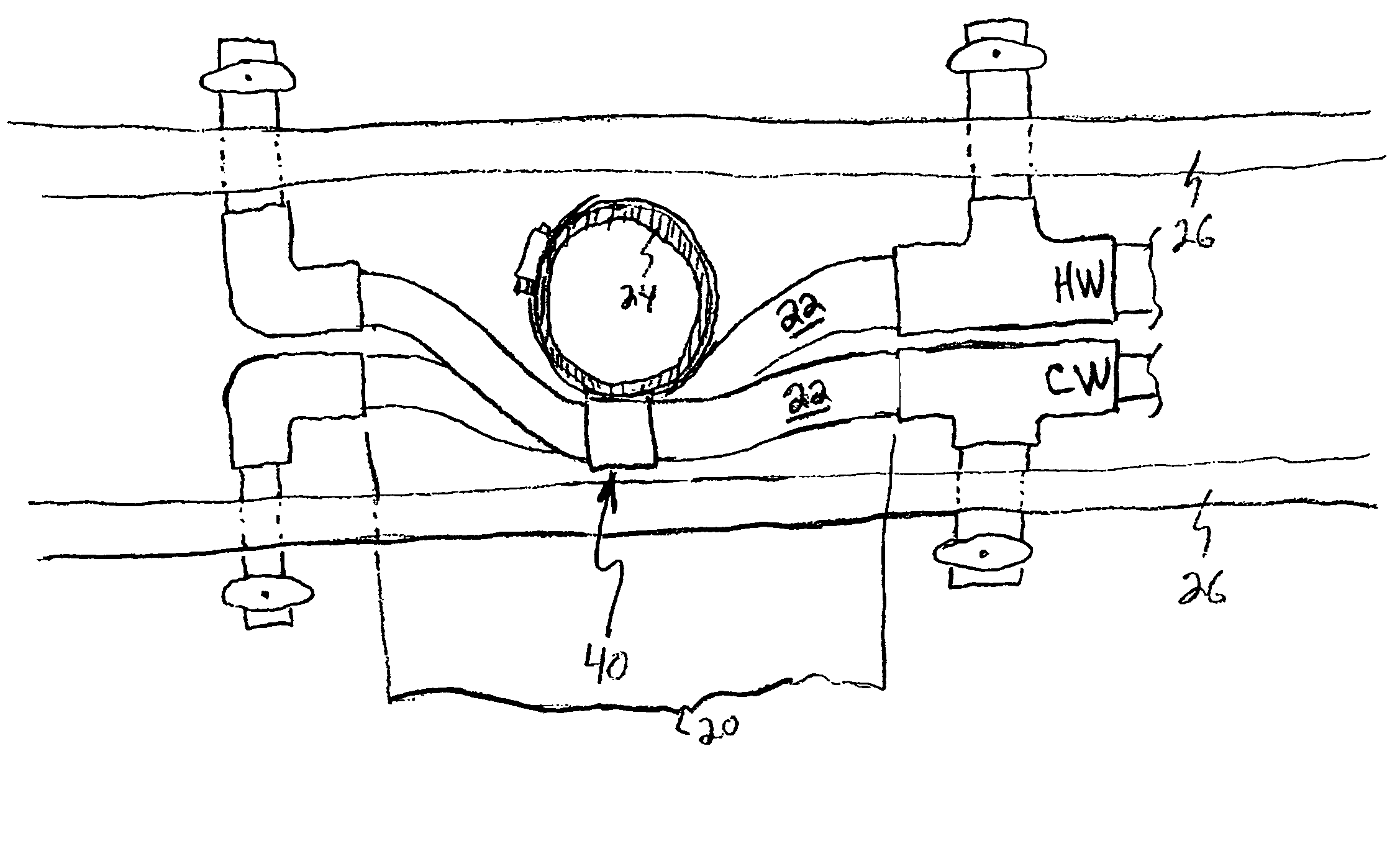
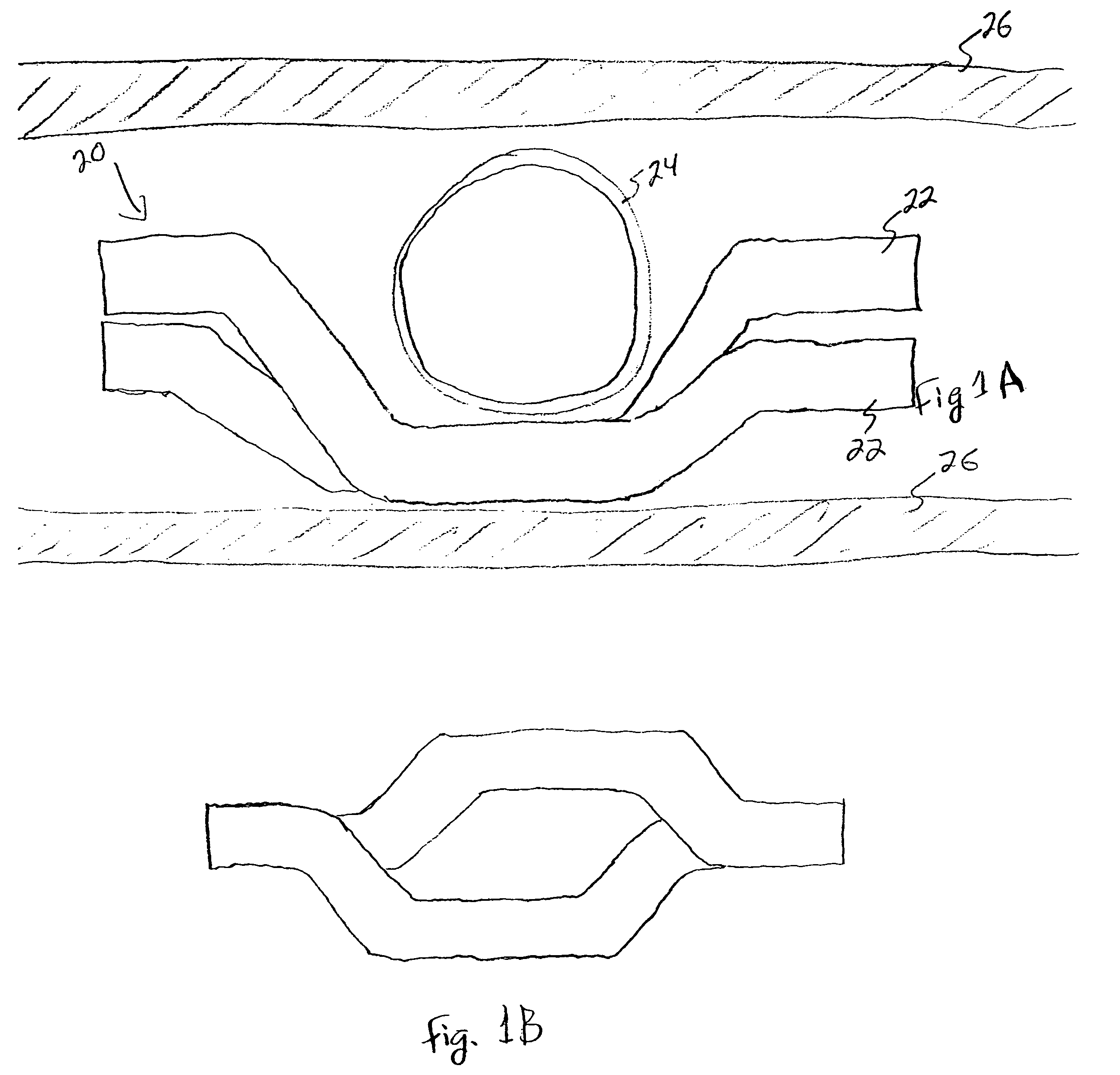
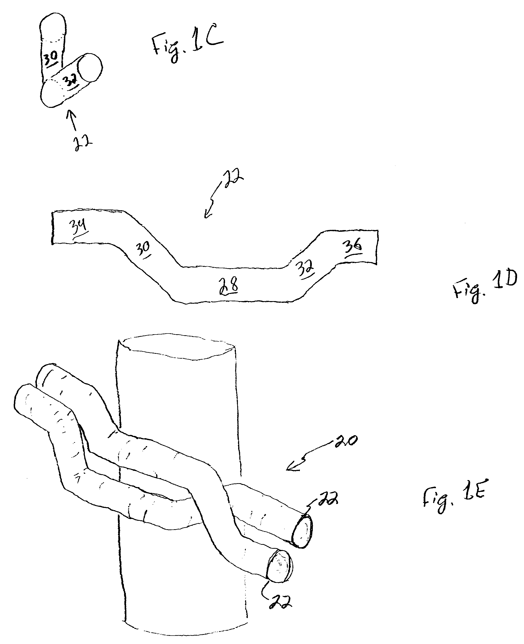
[0035]In its simplest form a hot-cold crossover manifold 20 comprises a pair of manifold tubes 22 wherein each tube 22 comprises a single piece of material that is bent such that when laid adjacent one another the ends of each tube 22 are next to one another but the tubes 22 cross over one another at a point between the two ends (FIGS. 1A, 1B, 2).

[0036]In one embodiment (FIGS. 3A, 3B, 4C) the tubes 22 are held fixed relative to one another, for example by a metal bracket welded to the tubes 22 (FIG. 4F). In another embodiment the manifold 20 simply comprises two appropriately-shaped tubes 22 that cross over and attach to the correct supply lines and wall fittings (FIG. 1A). In yet another embodiment (FIGS. 3A, 3B) the crossover manifold 20 also comprises a bracket 40 to which the tubes snap in place, wherein the brack...


PUM


Abstract

A crossover manifold system for hot and cold water faucet pairs arranged back to back on opposite sides of a partition, the system comprising a pair of manifold tubes, wherein each tube comprises a central section; a first intermediate section and a second intermediate section, wherein each intermediate section is adjacent to and angled with respect to the central section; and a first distal section and a second distal section, wherein each distal section is adjacent to and angled with respect to the first and second intermediate sections, respectively. The first and second distal sections are approximately parallel to one another, and the manifold tubes cross over one another.

Description

CROSS-REFERENCE TO RELATED APPLICATIONS[0001]None.BACKGROUND OF THE INVENTION[0002]1. Field of the Invention[0003]The present invention relates to plumbing fittings in general and in particular to a manifold assembly for aligning hot and cold water supply lines for back to back basins on opposite sides of a partition.[0004]2. Related Art[0005]In the plumbing trade and in particular in commercial buildings, plumbing fixtures are often situated directly opposite one another on opposite sides of a partition such as a wall in order to reduce the amount of plumbing lines that must be installed. Such arrangements might also be put in place on every floor of a multistory building so that the hot and cold water supply lines as well as drain / waste / vent pipes can run from floor to floor connecting to each fixture at each level with a minimum of plumbing lines.[0006]Given the standard supply line arrangement for a basin wherein the hot water faucet is always on one side and the cold water fauc...

Claims


Application Information

Patent Timeline
Patent Type & Authority Patents(United States)
IPC IPC(8): F16L5/00
CPCE03C1/021E03C1/12E03C2001/028Y10T137/698
Inventor GRAYBEAL, MICHAEL
Owner GRAYBEAL MICHAEL
Features
  • R&D
  • Intellectual Property
  • Life Sciences
  • Materials
  • Tech Scout
  • Unparalleled Data Quality
  • Higher Quality Content
  • 60% Fewer Hallucinations
Learn More