Method of and apparatus for controlling flashback in an introducer needle and catheter assembly

a technology of introducer needle and catheter assembly, which is applied in the direction of catheter, guide needle, other medical devices, etc., can solve the problems of inconvenient placement for healthcare workers and inability to be used to confirm

Inactive Publication Date: 2010-04-06
BECTON DICKINSON & CO
View PDF78 Cites 54 Cited by
  • Summary
  • Abstract
  • Description
  • Claims
  • Application Information

AI Technical Summary

Benefits of technology

[0006]It is an object of another aspect of the invention to provide a method of making an introducer needle and catheter assembly that includes a controlled, visible flashback rate in an extension tube. Specifically, catheter assembly may be designed to achieve initial flashback at the needle tip, as well as distinct confirmation flashback at a controlled rate when the catheter is located within the patient's vein.
[0014]In other implementations, it is desirable to size the annular space between the needle and the catheter (based, at least in part, on the viscosity of the fluid and the pressure of the fluid) to act as a throttle, restricting (and thereby controlling) the flow through the flow path and achieving the preferred flow rate through the extension tube. Alternatively, the notch may be sized such that it acts as the throttle. Further, the porosity of the plug in the extension tube may be designed such that it permits air to flow out of the tube at a rate which acts as a throttle by preventing the blood from entering the tube any faster.
[0017]In accord with yet another aspect of the invention, a method is provided for controlling flashback in an extension tube of an introducer needle assembly. A translucent catheter is provided having a proximal end, a distal end and a central bore extending from the proximal end to the distal end. A catheter hub is in fluid communication with the central bore and has a proximal end and a distal end connected to the proximal end of the catheter and a side port in fluid communication with the catheter hub. An extension tube is in fluid communication with the side port. The proximal end of an introducer needle extends from the distal end of a needle hub. The introducer needle adapted to be positioned within the catheter in an insertion position wherein the distal end of the introducer needle extends distally past the distal end of the catheter. A seal is affixed to the catheter hub and located proximal of the side port, sealing the proximal end of the catheter hub. The introducer needle has a cross sectional area that is less than the cross sectional area of the central bore such that an annular space is defined between the introducer needle and the catheter. A notch at the distal end of the introducer needle is located within the catheter when the introducer needle is in the insertion position such that fluid can communicate between the notch at the distal end of the introducer needle and the side port but is prevented from passing out of the proximal end of the catheter hub by the seal. The introducer needle, the notch and the central bore are sized to control the flow of fluid through the annular space, thereby controlling the flow of fluid through the extension tube.

Problems solved by technology

This location is inconvenient for the healthcare worker because, during insertion of the assembly into a patient, the healthcare worker's attention is directed to the distal tip of the needle.
Typically, flashback chambers are immediately filled with blood upon the initial access of the vein and cannot be used to confirm that the catheter assembly has maintained (or achieved again) access to the vein.

Method used


Image

  • Method of and apparatus for controlling flashback in an introducer needle and catheter assembly
  • Method of and apparatus for controlling flashback in an introducer needle and catheter assembly
  • Method of and apparatus for controlling flashback in an introducer needle and catheter assembly

Examples


Embodiment Construction

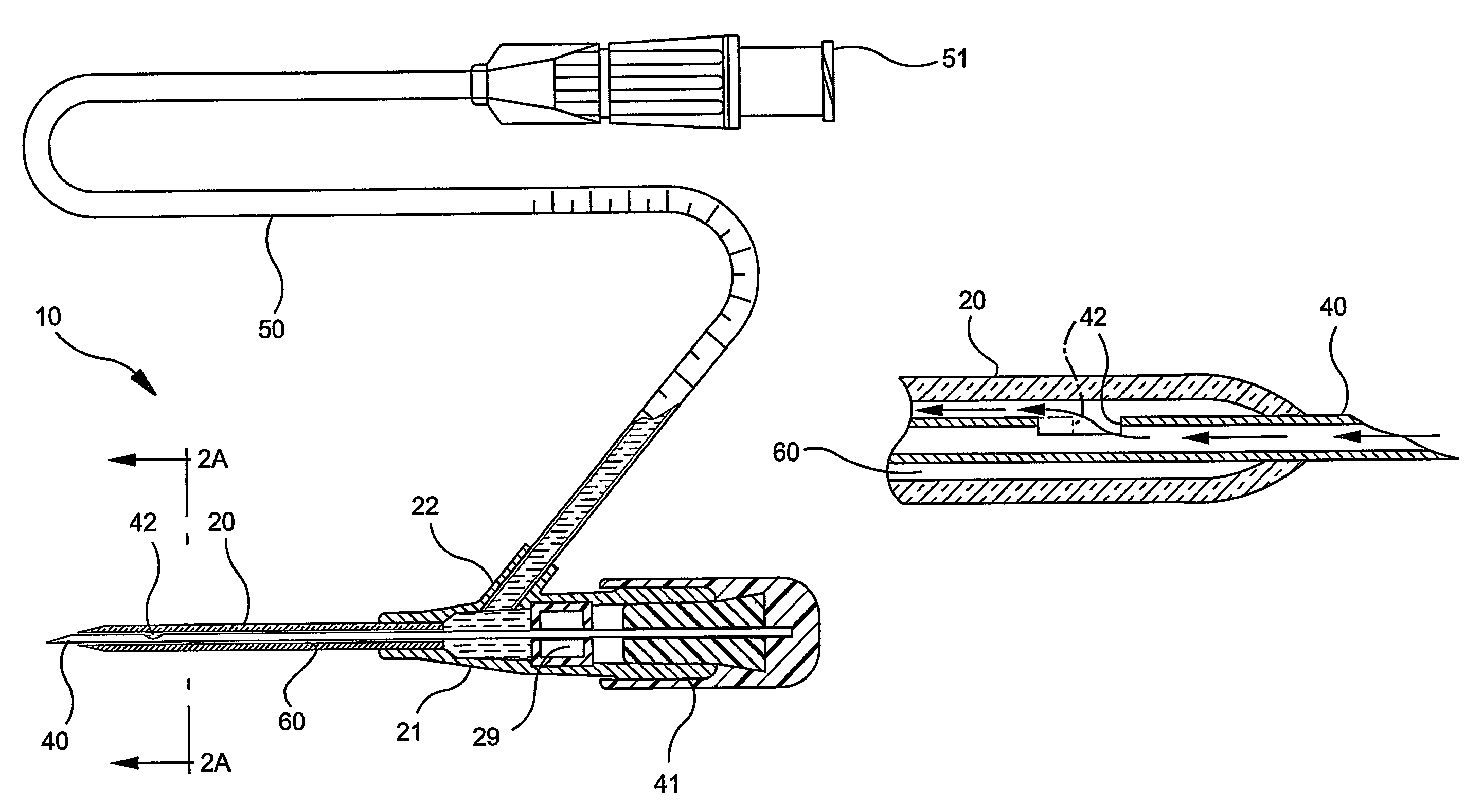
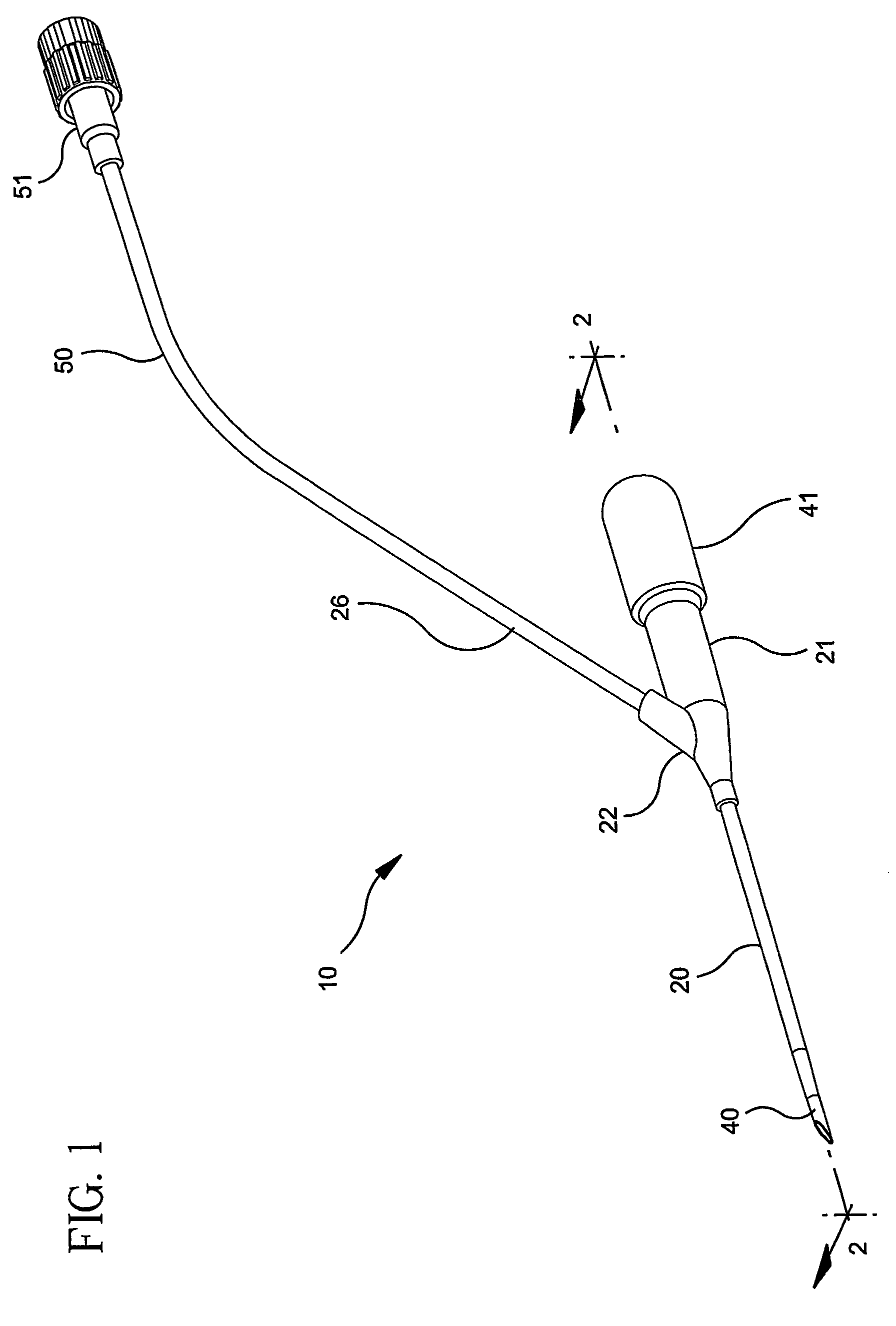
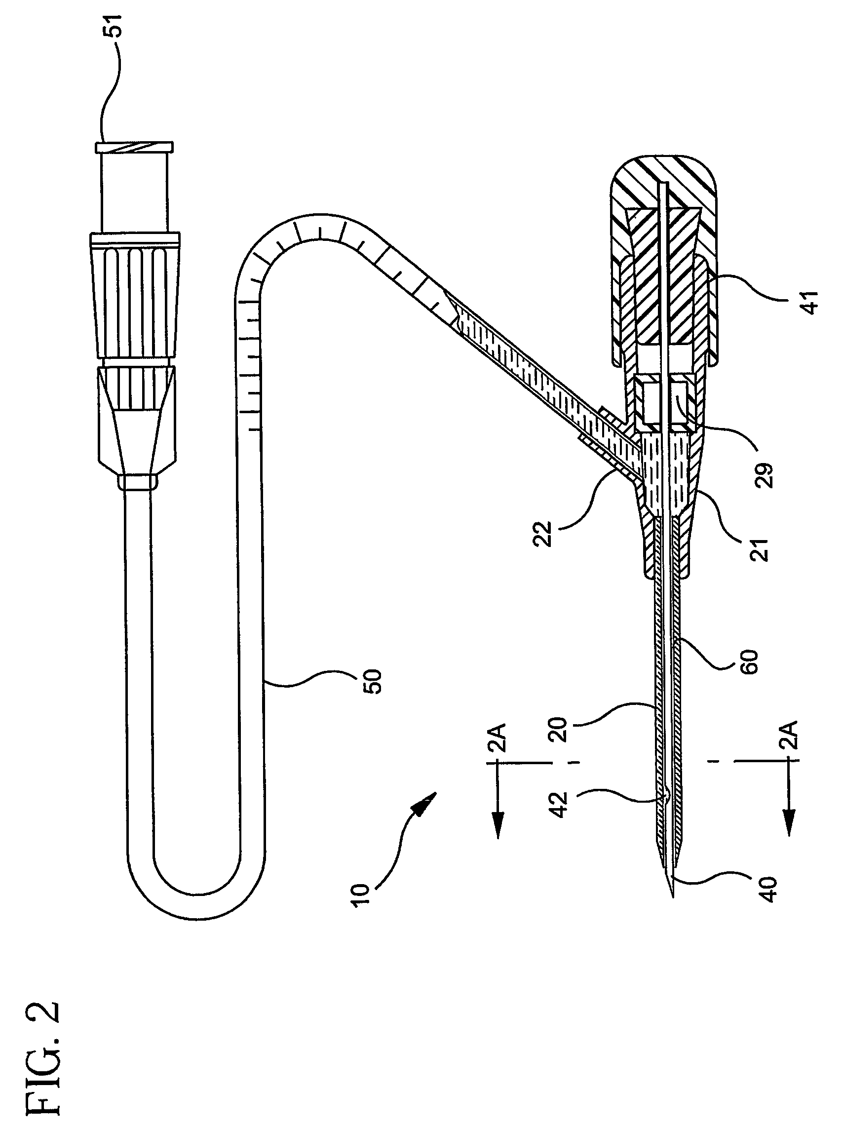
[0026]The catheter and introducer needle assembly 10 in accord with one implementation of this invention is shown in FIG. 1. As depicted, the assembly is an integrated catheter. It will be appreciated that aspects of the instant invention may be employed with other catheter and introducer needle assemblies, such as those disclosed in U.S. Pat. Nos. 4,326,519; 5,810,780; 5,935,110; 5,676,656; and 5,879,334, each incorporated herein by reference. In accord with one implementation of the invention, the catheter and introducer needle assembly includes catheter 20 affixed to catheter hub 21 and needle 40 affixed to needle hub 41. The catheter includes a central bore 120 having a cross sectional area and may be formed of translucent material (including transparent materials). As used herein, “translucent” materials shall be construed to include transparent materials, as well as materials that permit light to pass but not clearly enough to be deemed transparent.

[0027]The needle 40 has an o...


PUM


Abstract

A method is provided for controlling the fluid flow rate in an extension tube of an introducer needle assembly for use as confirmation flashback. The introducer needle assembly has a catheter attached to a catheter hub with a side port, an extension tube attached to the side port on the catheter hub, and an introducer needle with a notch adapted to be inserted into a bore in the catheter. A lumber extends through the needle and is in fluid communication with the notch. The needle has an outer diameter smaller than the diameter of the bore such that an annular space is defined between the catheter and the needle. The fluid, typically blood, is at a pressure and has a viscosity when the needle accesses it. A preferred minimum fluid velocity of the fluid through the extension tube is selected (preferably at least 1 inch per minute though the extension tube in certain applications). The notch and the annular space are sized based, at least in part, on the viscosity of the fluid and the pressure of the fluid to achieve the preferred flow rate though the extension tube.

Description

CROSS-REFERENCES TO RELATED APPLICATIONS[0001]This application is a 371 of PCT US / 03 / 19667 filed Jun. 20, 2003 which claims the benefit of provisional application 60 / 390,349 filed Jun. 21, 2002.FIELD OF THE INVENTION[0002]This invention relates to the field of catheter and introducer needle assemblies. Specifically, the invention relates to a method of and an apparatus for controlling flashback in an introducer needle and catheter assembly.BACKGROUND OF THE INVENTION[0003]Catheters, particularly intravenous (IV) catheters, are used for directing fluid into or withdrawing fluid from a patient. The most common type of IV catheter is an over-the-needle IV catheter. As its name implies, an over-the-needle IV catheter is mounted over an introducer needle having a sharp distal tip. With the distal tip of the introducer needle extending beyond the distal tip of the IV catheter, the assembly is inserted through the patient's skin into a vein. Once placement of the assembly in the vein is ve...

Claims


Application Information

Patent Timeline
Patent Type & Authority Patents(United States)
IPC IPC(8): A61M31/00A61M25/00A61M25/06
CPCA61M25/0693
Inventor BRIMHALL, GREG L.
Owner BECTON DICKINSON & CO
Why Eureka
Try Eureka