Phased array ultrasonic water wedge apparatus

a phased array and ultrasonic technology, applied in the direction of instruments, magnetic property measurements, and analysis of solids using sonic/ultrasonic/infrasonic waves, can solve the problems of time-consuming rescans or missed defect detections, contact between the phased array ultrasonic transducer and the specimen being examined,

Inactive Publication Date: 2010-04-13
GENERAL ELECTRIC CO
View PDF19 Cites 41 Cited by
  • Summary
  • Abstract
  • Description
  • Claims
  • Application Information

AI Technical Summary

Problems solved by technology

Problems are sometimes experienced with the setup of the manipulator that delivers the ultrasonic transducers to the weld, and more importantly with the contact between the transducers and the specimen being examined.
If continuous contact between the transducer and the pipe is not maintained, the scan data collected will be flawed which can result in time consuming rescans or missed defect detections.
One major problem that still exists is the contact between the phased array ultrasonic transducer and the specimen being examined.
However, other issues, for example, improper scanner setup and irregularities in the pipe surface can also effect inspection accuracy.

Method used


Image

  • Phased array ultrasonic water wedge apparatus
  • Phased array ultrasonic water wedge apparatus
  • Phased array ultrasonic water wedge apparatus

Examples


Embodiment Construction

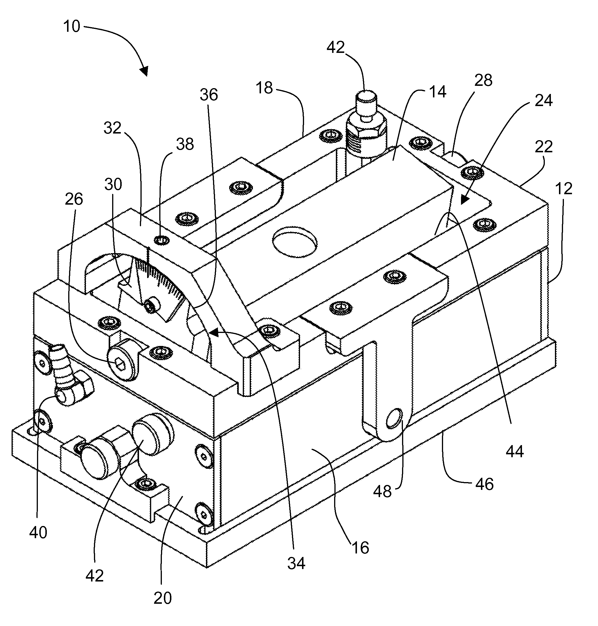
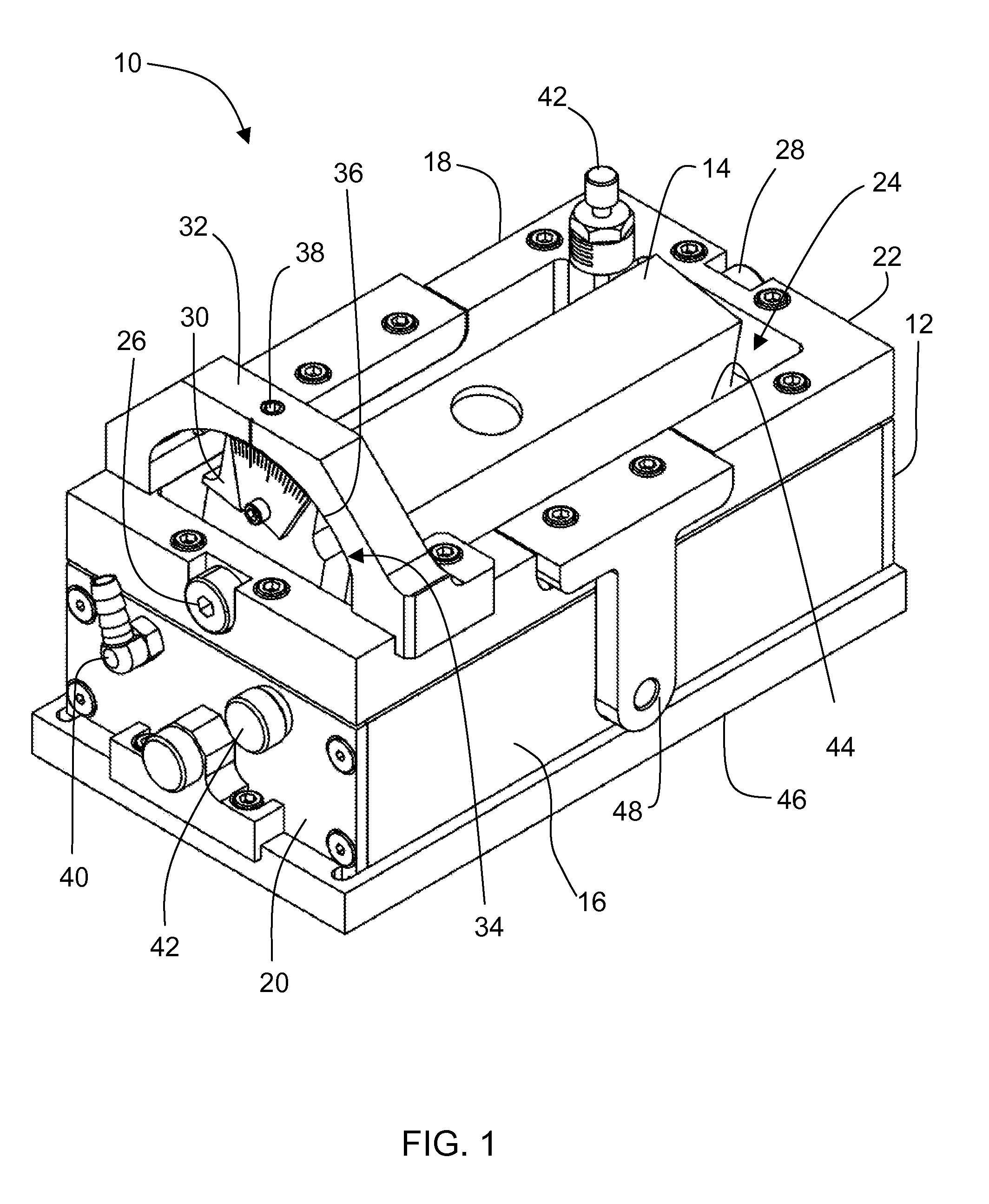
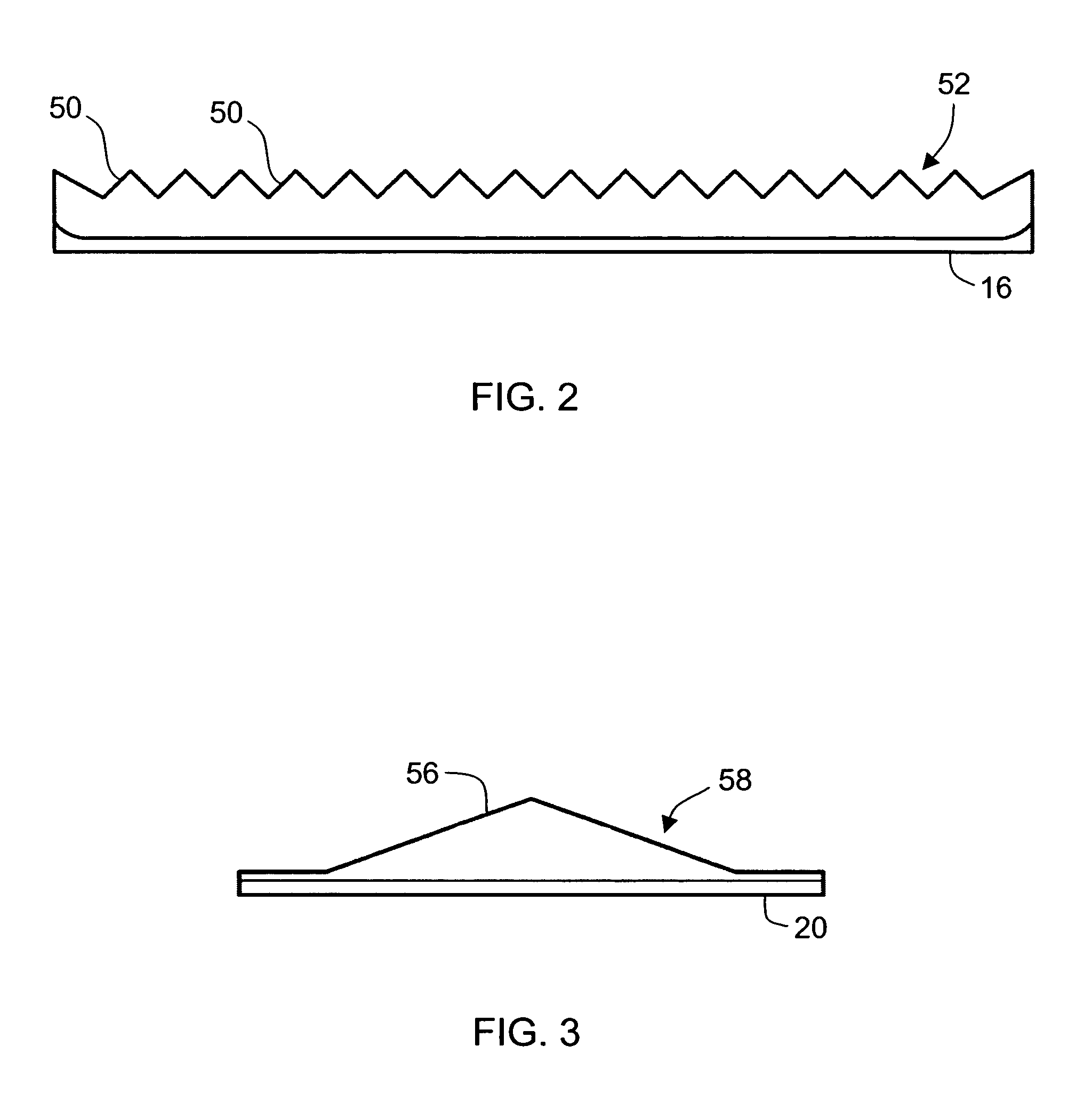
[0012]A phased array ultrasonic probe assembly that includes a housing and a phased array transducer supported inside the housing is described below in detail. The housing includes opposing side walls having a plurality of “saw tooth” projections, and opposing end walls each having a at least one “saw tooth”, or triangle shaped, projection. The housing holds the phased array ultrasonic transducer in a standing column of water. The water fills the volume between the bottom of the transducer and the material that is being examined and permits for the ultrasonic sound waves to travel from the probe directly to the material with no break in contact. Sound exits the transducer at a predetermined angle and travels through the water until it comes in contact with the material where a velocity change is experienced. The change in speed causes the sound to refract as it penetrates that material permitting the weld volume to be inspected using the predetermined angle. To minimize the amount o...


PUM

PropertyMeasurementUnit
frequencyaaaaaaaaaa
diameteraaaaaaaaaa
flexibleaaaaaaaaaa

Abstract

A phased array ultrasonic probe assembly includes, in an exemplary embodiment, a housing and a phased array transducer supported inside the housing. The housing includes a first side wall and an opposing second side wall, and a first end wall and an opposing second end wall. The first and second side walls and the first and second end walls define a housing cavity in which the phased array transducer is positioned. The first and second side walls each have an inside surface that include a plurality of projections.

Description

BACKGROUND OF THE INVENTION[0001]This invention relates generally to ultrasonic inspection of dissimilar metal welds, and more particularly ultrasonic inspection of dissimilar metal welds with phased array transducers.[0002]Pipe welds in, for example, nuclear reactors, have been examined with ultrasonic transducers using 45° and 60° refracted longitudinal waves. These angles have been established as the “norm” based on the weld configurations, ultrasonic theory, and field experience. The pipes are raster scanned in four directions to completely examine the weld volume which is very time consuming. Problems are sometimes experienced with the setup of the manipulator that delivers the ultrasonic transducers to the weld, and more importantly with the contact between the transducers and the specimen being examined. If continuous contact between the transducer and the pipe is not maintained, the scan data collected will be flawed which can result in time consuming rescans or missed defec...

Claims


Application Information

Patent Timeline
Patent Type & Authority Patents(United States)
IPC IPC(8): G01N29/04G01N29/32
CPCG01N29/225G01N29/262G01N2291/2634G01N29/04
Inventor MCGRATH, MATTHEWGALBALLY, DAVIDJOHNSON, PAULDAVIS, TREVORMITCHELL, III, WALTER
Owner GENERAL ELECTRIC CO
Why Eureka
Try Eureka