
Bicycle handlebar with removable and adjustable aerobar

a technology of aerobars and bicycle handles, which is applied in the direction of cycle equipment, steering devices, other supporting devices, etc., can solve the problems of difficult installation and removal of many previously known aerobars

Inactive Publication Date: 2010-04-20
COMPOSITECH
View PDF96 Cites 46 Cited by
  • Summary
  • Abstract
  • Description
  • Claims
  • Application Information

AI Technical Summary

Benefits of technology

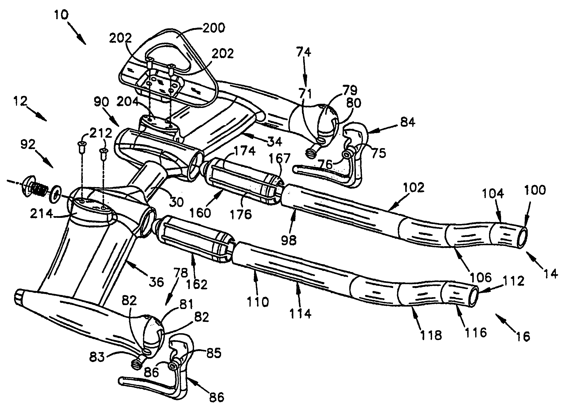
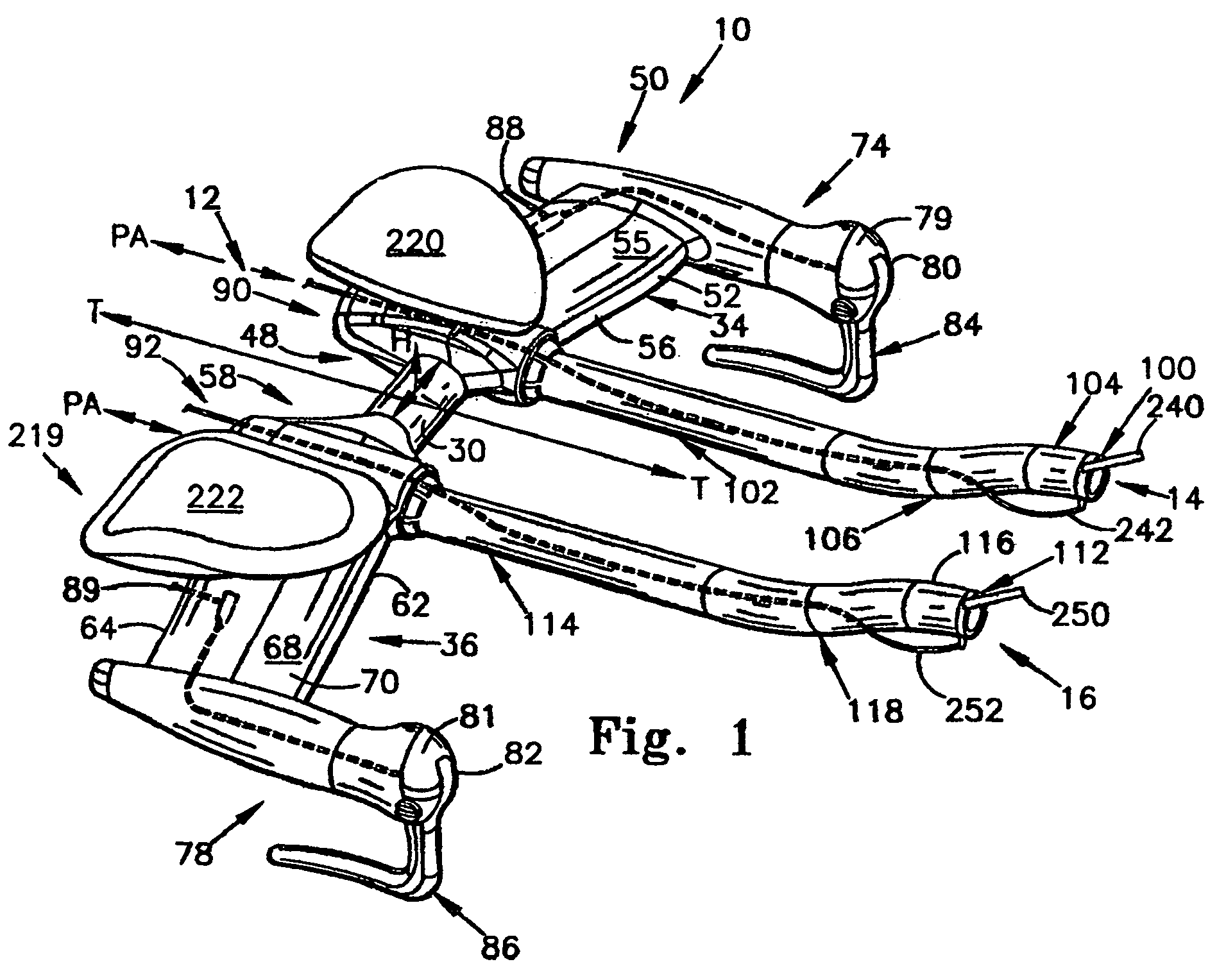
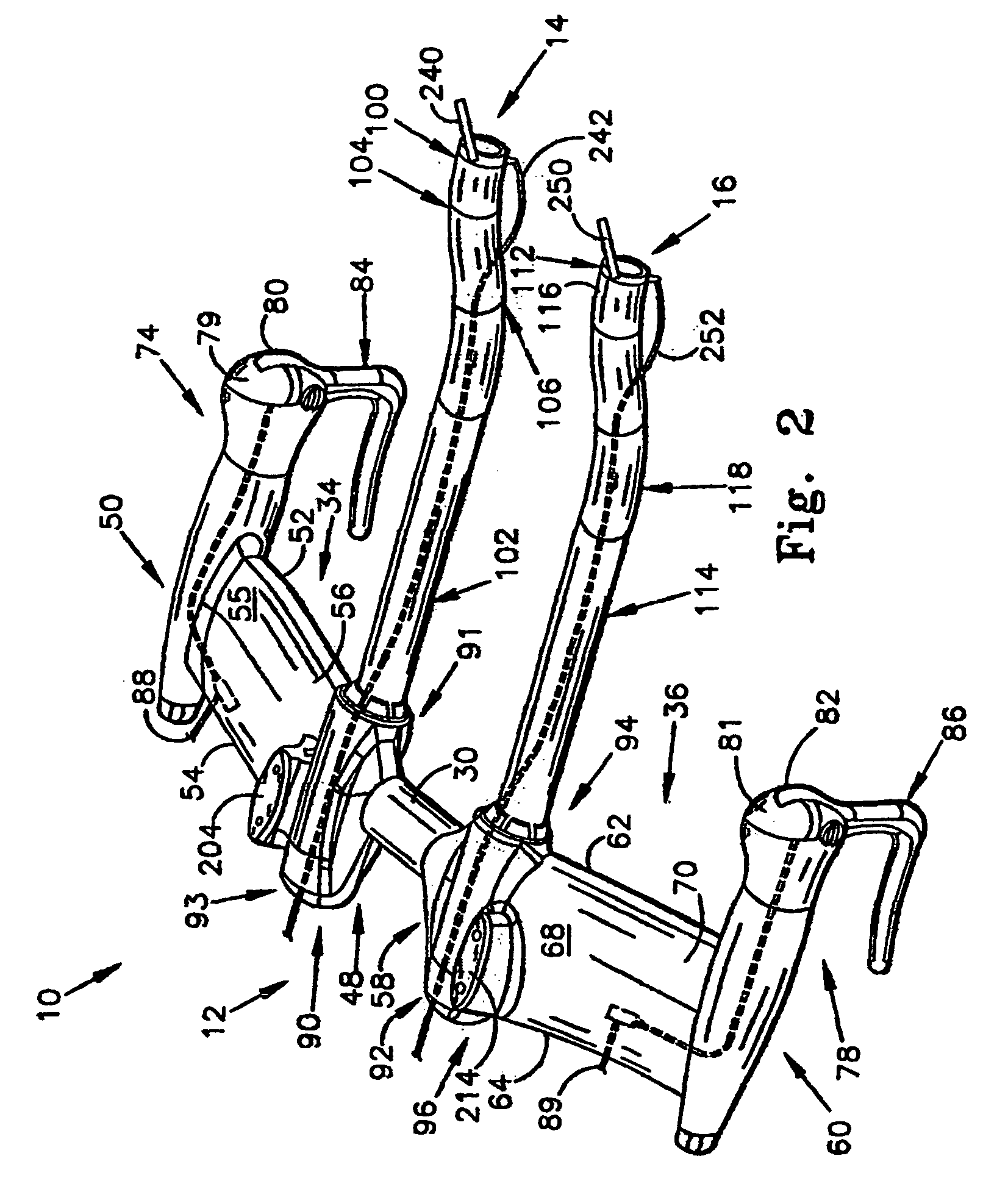
[0019]The first laterally extending member includes an aerobar clamping mechanism, and the second laterally extending member includes a second aerobar clamping mechanism. Each of the aerobar clamping mechanisms includes a tapered receiving sleeve having an axis that is generally parallel to the travel axis of the handlebar. A collet having a major axis that extends in a plane generally parallel to the direction of travel of the bicycle is receivable within the receiving sleeve. The collet includes a plurality of axially extending slots that permits the diameter of the collet to be varied. Each of the collets include an aerobar receiving slot, having a major axis that is generally co-linear with, or slightly offset from, or parallel to the axis of the collet, and is provided for receiving an aerobar member. An axial mover member can be coupled to the collet, for axially moving the collet within the aerobar receiving sleeve. Axial movement of the collet within the aerobar receiving sleeve serves to tighten and increase the grip of the collet upon the aerobar.
[0020]Preferably, the axis of the collet is offset by about three degrees from the axis of the aerobar receiving sleeve. This axial offset promotes an enhanced adjustability of the aerobars as it allows the aerobars to be adjusted to tilt upwardly, downwardly, inwardly or outwardly. Because of the nature of the collet, these adjustments can be made over a 360 degree range of various adjustments. Particularly, rotational orientation of the collet within the tapered receiving sleeve of the aerobar changes the axial position of the collet axis relative to the aerobar axis to provide the various adjustments. In one form, the handlebar includes a collet receiver for disposing the collet along a first axis, and wherein the collet is capable of receiving an aerobar such that the aerobar is disposed along a second axis offset from the first axis.
[0022]Another feature of the present invention is that the handlebar of the present invention provides a reduced-drag handlebar that is believed by the Applicants to have enhanced aerodynamic properties when compared to traditional tube-type handlebars.
[0023]A further feature of the present invention is that the clamping mechanism permits the aerobars to be easily removed and attached to the aerobar clamping mechanisms.
[0025]One facet of the adjustment enables the aerobars to be rotated, about their long axis, so that their handgrip portions can be rotated into a position that the user finds most comfortable. Another facet of the adjustability of the aerobars of the present invention, is that the forwardly extending segment of the aerobars can be adjusted about 360 degree axis so that, for example, the aerobars can be titled upwardly, downwardly, inwardly (with respect to the primary travel axis of the bicycle), and outwardly. Further, the 360 degree adjustability of the device permits the aerobars to be adjusted, for example, upwardly and inwardly, upwardly and outwardly, downwardly and outwardly, and downwardly and inwardly, among other adjustments.
[0026]Also, the clamping mechanism of the present invention enables the effective length of the aerobars to be adjusted, so that they can, for example, accommodate users having different lengths of forearms.

Problems solved by technology

Many previously known aerobars suffer the deficiency of being difficult to install as well as difficult to remove.
These difficulties cause problems, as certain circumstances exist wherein a rider prefers to remove the aerobars from his handlebar.

Method used


Image

  • Bicycle handlebar with removable and adjustable aerobar
  • Bicycle handlebar with removable and adjustable aerobar
  • Bicycle handlebar with removable and adjustable aerobar

Examples


second embodiment

[0095]A second embodiment collet 700 is shown in FIG. 21. Collet 700 is similar to collets 160 and 602, insofar as collet 700 includes a proximal end 702, a distal end 704, an outer surface 706, and an inner surface 708. Also similarly, inner surface 708 defines a sleeve for receiving the proximal end of an aerobar; and a series of parallel, blind slots 710 are provided for enabling the user to vary the radial diameter of the collet 700, in a manner similar to that described above in connection with collet 160.

[0096]In co-linear collet 700, the 6:00 portion 714 and 12:00 portion 706 have generally the same thickness throughout their entire length. Additionally, it will be noted that the interior surface 708, and exterior surface 706 are co-axial, such that both share a common axis CO, CS.

[0097]Because of this co-axial nature of the inner surface 706, 708, the rotation of co-linear collet 700 about its axis CO, CS, within the receiving sleeve of the handlebar, will not cause the axis...

first embodiment

[0105]The integral collet 314 includes a first proximal end 357, a second or distal end 358, and a smooth, generally cylindrical interior surface that is sized and configured for receiving the proximal end 380 of the aerobar 303 therein. The collet 314 also includes a threaded outer surface 361, and a plurality of spaced, axially extending slots 362, with each slot 362 having an open end 364 adjacent to the distal end 358 of the collet 314. While not necessarily so, the integral collet 314 preferably operates similarly to the collets 160, 162 shown in connection with the first embodiment, and can be configured similarly to any of collets 160, 601, or 700.

[0106]The generally cylindrical collar 315 is sized and configured to interiorly receive the collet 314. The collar 315 includes a generally cylindrical, threaded inner surface 372 that defines an axially extending passageway 373 for receiving the exterior surface of the collet 314. The threads 361 of the collet engage the interior ...

third embodiment

[0111]an aerobar clamp system is depicted in FIGS. 16-19. FIG. 16 shows a pair of aerobar clamp systems or assemblies 400, 402, mounted onto handlebars 404 for attaching aerobars 403, 405 to the handlebar 404. Forearm rest assemblies 410, 412 may be provided and mounted to respective aerobar clamp systems 400, 402. The two aerobar clamp systems 400, 402 are generally identical. As such, features discussed with respect to one aerobar clamp system are applicable to the other aerobar clamp system. Moreover, the two forearm rest assemblies 410 and 412 are generally identical. As such, features discussed with respect to one forearm rest assembly are applicable to the other forearm rest assembly.

[0112]As shown in FIG. 17, aerobar clamp system 400 includes an attachment member 420 that is comprised of a generally tubular body 422. The tubular body 422 is adapted to be received and attached onto the handlebar 404. To this end, a proximate end 424 of the tubular body 422 includes a curved no...


PUM


Abstract

A handlebar for a bicycle has first and second laterally extending portions disposed outboard of a central attachment portion. Each of the first and second laterally extending portions is preferably winged-like in configuration to provide reduced air resistance. The first laterally extending portion includes an aerobar clamping mechanism, and the second laterally extending portion includes a second aerobar clamping mechanism. Each aerobar clamping mechanism includes a tapered receiving sleeve having an axis that is generally parallel to a travel axis of the handlebar. A collect having a major axis that extends in a plane generally parallel to the direction of travel of the bicycle is receivable within the receiving sleeve. The collet includes a plurality of axially extending slots that permits the diameter of the collet to be varied. The collet includes an aerobar receiving slot having a major axis that is generally co-linear with the axis of the collect, and is provided for receiving an aerobar. An axial mover member can be coupled to the collect, for axially moving the collect within the aerobar receiving sleeve. Axial movement of the collect within the aerobar receiving sleeve serves to tighten and increase the grip of the collect upon the aerobar.

Description

I. PRIORITY CLAIM[0001]The instant application claims priority to Ording and Poertner, U.S. Provisional Patent Application No. 60 / 623,163 filed 29 Oct. 2004.II. TECHNICAL FIELD OF THE INVENTION[0002]The present invention relates to components for a human powered vehicle, such as bicycles, and more particularly, to a novel handlebar for use with a human powered vehicle, such as a bicycle.III. BACKGROUND OF THE INVENTION[0003]Most human powered vehicles, such as bicycles, include a handlebar mechanism to enable the user to steer the vehicle. A handlebar mechanism typically includes a shaft member that extends through the frame, and is coupled to the fork of the bicycle, so that rotational movement of the shaft causes rotational movement of the bicycle wheel. The stem member is connected onto the shaft, and extends upwardly, and, usually forwardly. The stem includes a clamping member, that permits a handlebar to be clamped to the stem.[0004]The handlebars on most bicycles have a major ...

Claims


Application Information

Patent Timeline
Patent Type & Authority Patents(United States)
IPC IPC(8): B62K21/12
CPCB62K21/12B62K21/125Y10T74/20822Y10T74/2078B62J11/13
Inventor ORDING, ANDREWPOERTNER, JOSHUA R.
Owner COMPOSITECH
Learn More