Temporary attachment for use with pipe hangers

a technology for temporary attachments and pipes, which is applied in the direction of manufacturing tools, machine supports, other domestic objects, etc., can solve the problems of not being strong enough not being able to rotate pipes normally, and not being able to withstand the weight of pipes and contents, etc., to facilitate the longitudinal movement of pipes, quick and easy mounting, and quick and easy removal

Inactive Publication Date: 2010-04-20
RIIBE GARY +1
View PDF16 Cites 13 Cited by
  • Summary
  • Abstract
  • Description
  • Claims
  • Application Information

AI Technical Summary

Benefits of technology

[0007]The temporary attachments which are attached to all of the pipe hangers are quickly and easily mounted on the pipe hangers and are quickly and easily removed from the pipe hangers once the pipes have been welded together and placed in their proper position.
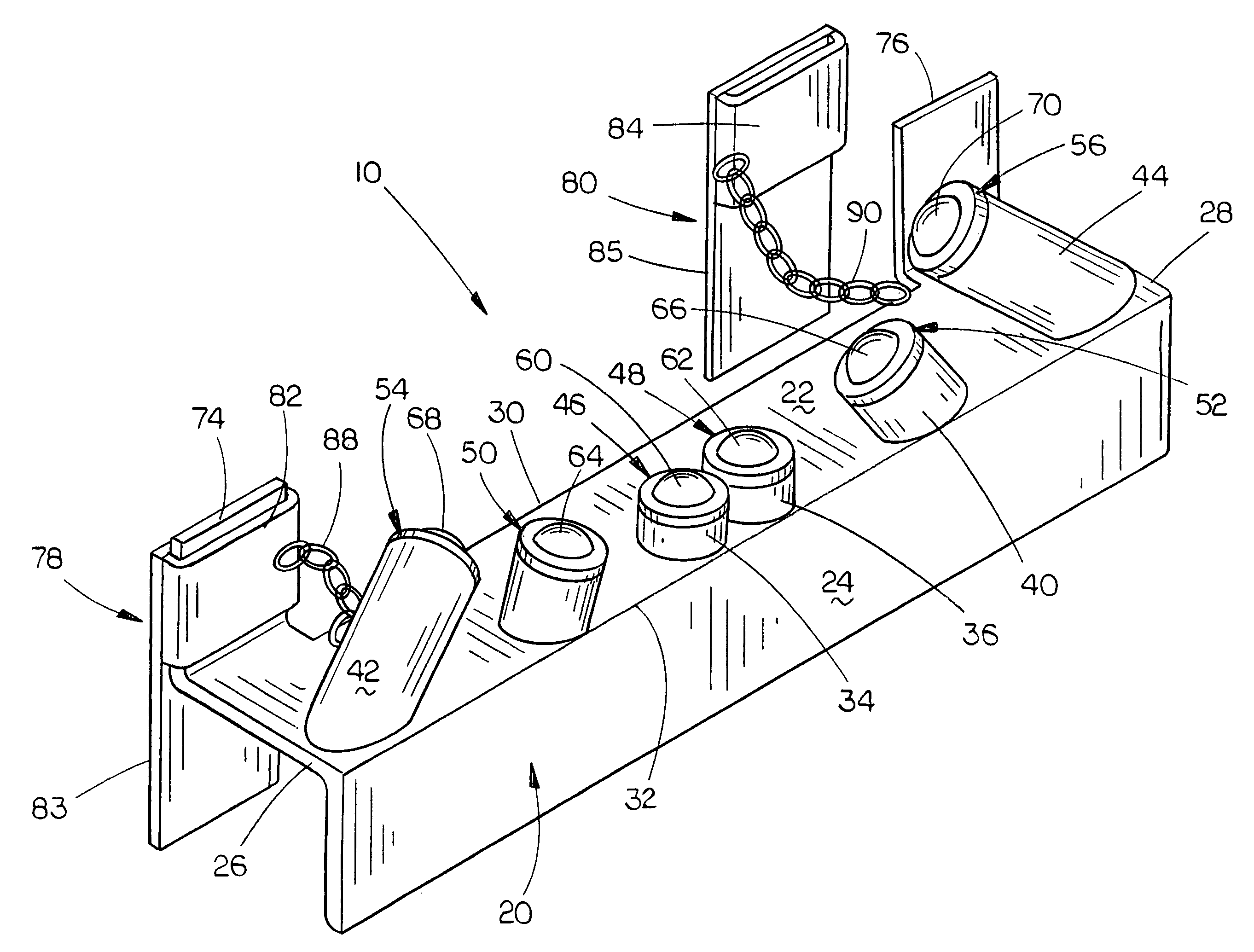
[0008]Therefore, it is a principal object of the invention to provide a temporary attachment for use with pipe hangers which not only facilitates the longitudinal movement of pipes through the pipe hangers but which also permits the pipes to be rotatably mounted with respect to the pipe hangers for welding.

Problems solved by technology

At some point, it is necessary to weld the ends of the pipe lengths together to form a pipe line, which may be difficult since the ends of the pipes may be located in a bridge work or the like, which means that the welder must attempt to reach around the ends of the adjacent pipes to weld the pipes together.
It is not normally possible to rotate the pipes to facilitate the welding process in close quarters due to the size and weights of the pipes.
Further, those pipe hangers which have rollers mounted thereon for lengthwise movement of the pipes with respect to the pipe hangers, those rollers are a permanent part of the hangers which can add to the cost of the installation and which may not be sturdy enough to withstand the weight of the pipes and contents thereof over a long period of time.

Method used


Image

  • Temporary attachment for use with pipe hangers
  • Temporary attachment for use with pipe hangers
  • Temporary attachment for use with pipe hangers

Examples


Embodiment Construction

[0018]In FIG. 1, the preferred embodiment of the temporary attachment of this invention is referred to generally by the reference numeral 10, which is designed to be used with many shapes and designs of conventional pipe hangers such as that illustrated in the drawings and which are referred to generally by the reference numeral 12. Normally, the pipe hangers 12 will include at least a pair of vertically disposed and horizontally spaced-apart supports 14 and 16 which will normally be I-beams when large diameter pipes are to be supported from a supporting structure such as a ceiling or bridge work. Normally, a horizontally extending support member 18 will be secured to and will extend between the lower ends of the supports 14 and 16. Again, if large pipes are being hung, the horizontal support 18 will usually be an I-beam.

[0019]Normally, as seen in FIG. 3, a plurality of the pipe hangers 12 will be secured to a suitable support structure such as a ceiling or the like and which will b...


PUM


Abstract

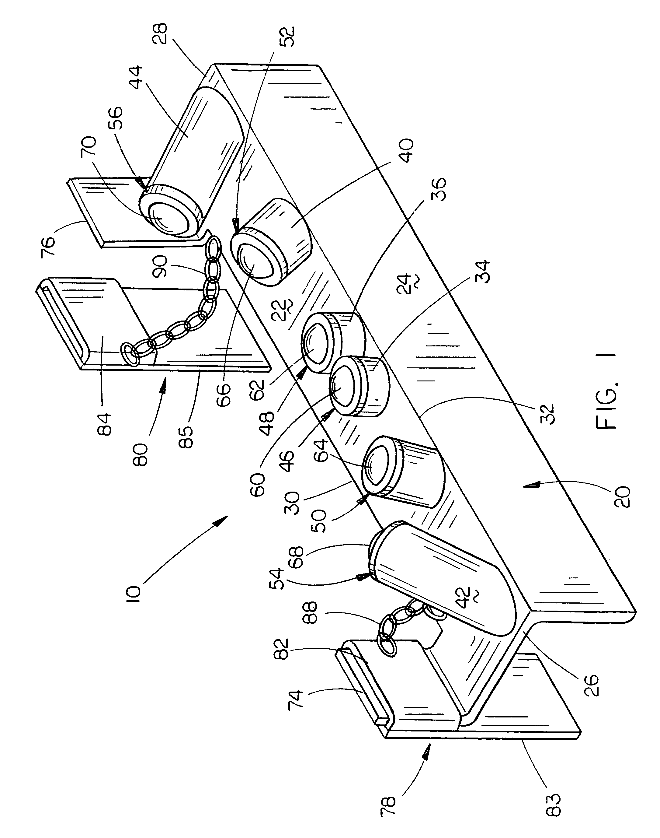
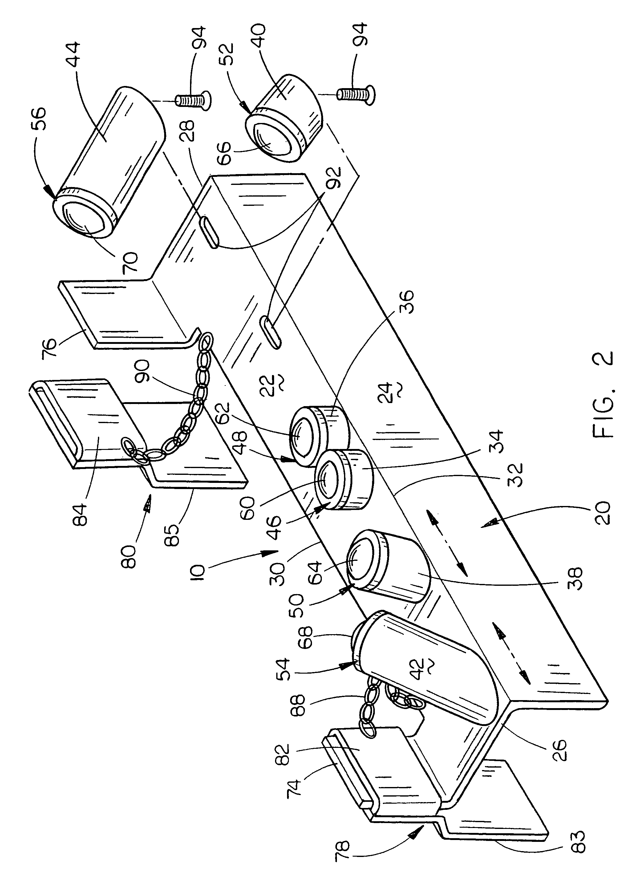
A temporary attachment for use with pipe hangers is disclosed which includes an elongated angle member which is supported upon the lower end of a pipe hanger and which has a plurality of ball transfer units positioned thereon which support the pipe being hung. The ball transfer units not only permit the longitudinal movement of the associated pipe with respect to the pipe hanger but also permits the pipe to be rotated about its longitudinal axis with respect to the pipe hanger.

Description

BACKGROUND OF THE INVENTION[0001]1. Field of the Invention[0002]This invention relates to a temporary attachment for use with a pipe hanger and more particularly to a temporary attachment which facilitates the pulling of pipes through pipe hangers and even more particularly to a temporary attachment for use with pipe hangers which enables pipes to be moved longitudinally through the pipe hangers and which permits rotational movement of the pipes with respect to the pipe hangers during the welding of the pipes together.[0003]2. Description of the Related Art[0004]Pipe hangers are often used for suspending pipes from ceilings or other structures such as bridge works, etc. Typically, a plurality of pipe hangers are used in a spaced-apart parallel arrangement to suspend pipes from ceilings or other structures. When the pipes are large-diameter pipes and thus very heavy, large-diameter pipes are to be suspended from a support structure, the pipe hangers may be spaced apart every ten feet...

Claims


Application Information

Patent Timeline
Patent Type & Authority Patents(United States)
IPC IPC(8): F16L3/16
CPCF16L1/09F16L3/18F16L3/16F16L1/10
Inventor RIIBE, GARYANDERSON, MARISSA R.
Owner RIIBE GARY
Why Eureka
Try Eureka