Quick-release worklight mounting

Active Publication Date: 2011-05-10
POLLUX LIGHTING
View PDF7 Cites 9 Cited by
  • Summary
  • Abstract
  • Description
  • Claims
  • Application Information

AI Technical Summary

Benefits of technology

[0003]The present invention provides a quick-release mounting mechanism for a worklight enabling the worklight to be quickly and easily mounted on and demounted from a tripod support stand an

Problems solved by technology

Although conventional, the use of such knobs is inconvenient at best, is often awkward because of the lack of space to get a good grip on

Method used


Image

  • Quick-release worklight mounting
  • Quick-release worklight mounting
  • Quick-release worklight mounting

Examples


Example

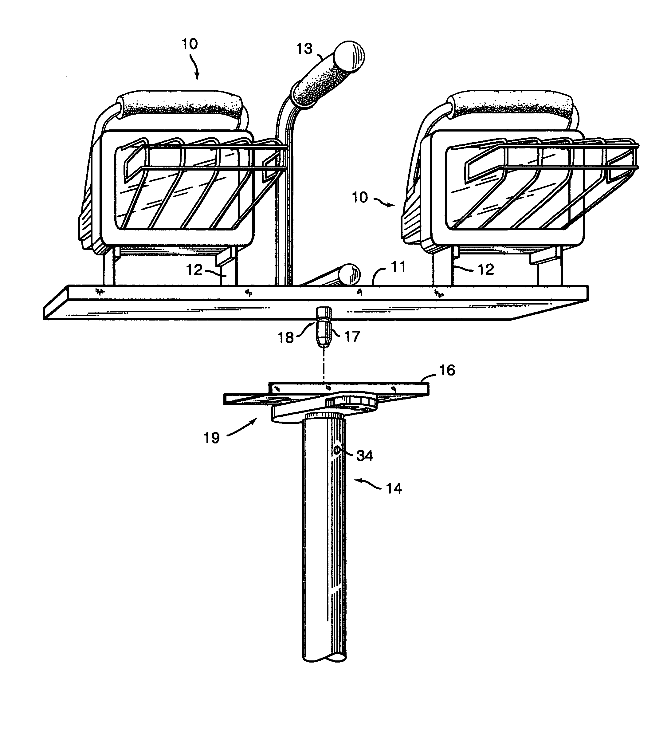
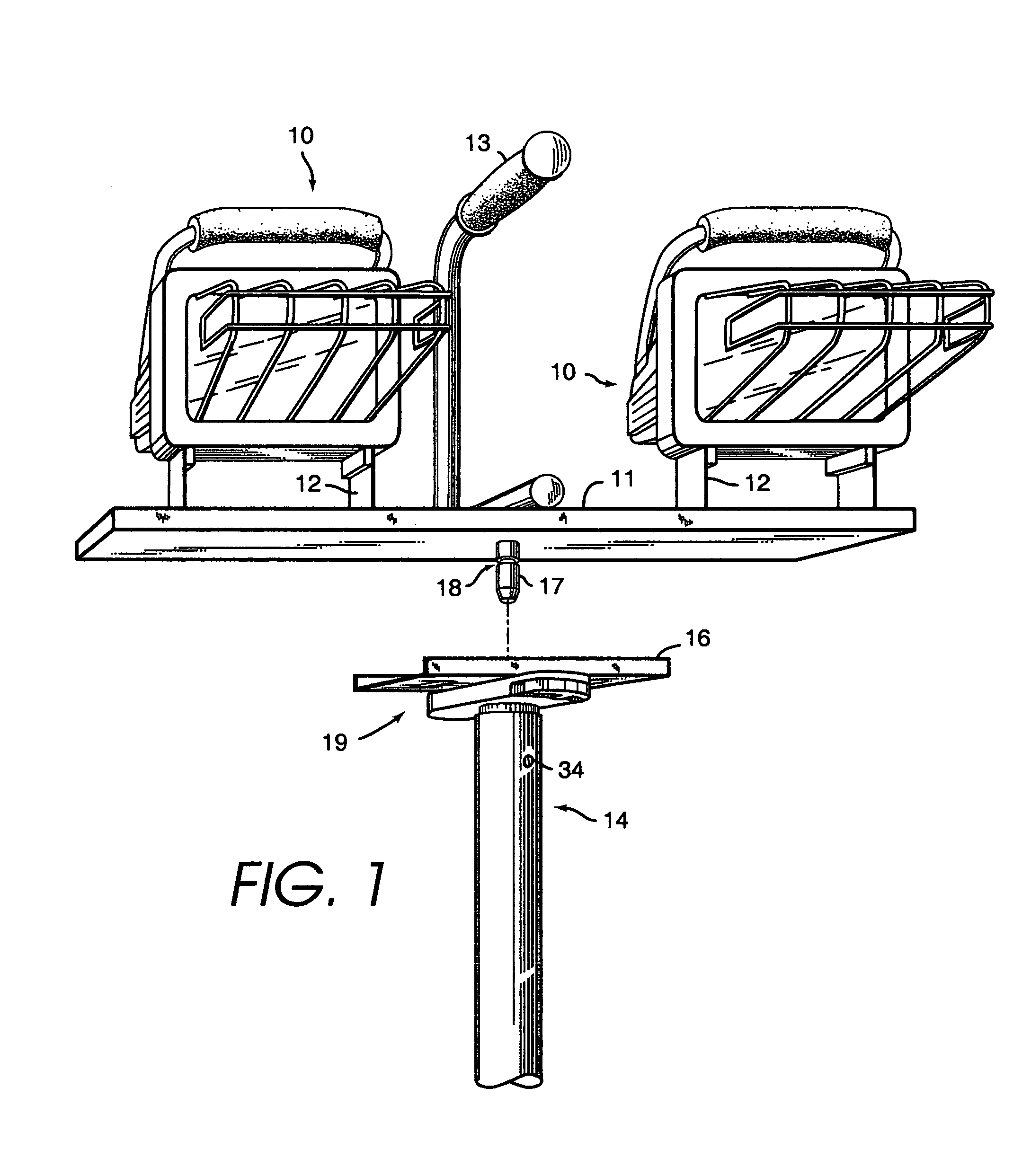
[0011]FIG. 1 shows an overall view of a dual-head worklight incorporating an embodiment of a quick-release mounting mechanism according to the invention for mounting and demounting the worklight to and from a support stand. Such a mounting is referred to here as a detachable mounting, meaning that it permits the worklight to be readily attached to and detached from the support in the ordinary course of worklight usage.

[0012]The worklight of FIG. 1 includes a pair of worklight heads 10, which are mounted on a base 11 through U-shaped mounting brackets 12. A handle 13 is secured to the base for carrying and positioning the worklight. As explained below, the worklight is adapted at the underside of base 11 to be mounted on a support 14, the upper portion of which is shown in FIG. 1. A common form of support used with worklights is a tripod support stand. The particular form of support stand is not important here, and for purposes of explanation only the upper portion of the stand need ...


PUM


Abstract

A quick-release mounting mechanism for a worklight enabling the worklight to be quickly and easily mounted on and demounted from a tripod support stand and enabling an individual worklight head to be quickly and easily mounted on and demounted from a base stand or other support member such as the handle of a spring clamp or other clamp member. The mounting mechanism includes a latch member on the worklight base or on an individual worklight head that cooperates with an actuator mounted in the support stand or other support member. The latch member is received in a hole in the support and the actuator is formed to engage a catch on the latch member when the worklight or individual worklight head is in position on the support. In particular, the actuator is mounted in the support for movement between a latching position and a release position, and the latch member and actuator are formed to engage one another when the actuator is in its latching position so as to hold the worklight or individual worklight head on the support. A spring arrangement in the support urges the actuator into its latching position, and the actuator is provided with an engagement member by which a user can urge the actuator into its release position for quick release of the worklight or the head from the support.

Description

BACKGROUND OF THE INVENTION[0001]The present invention relates to worklights and is more particularly directed to arrangements for mounting and demounting a worklight from a support structure such as a tripod or other supporting base.[0002]Worklights have become popular for use in such varied settings as construction jobs, industrial plants, automotive and auto body repair shops, artist and photographic studios, and projects around the home. A typical worklight has one or two, or sometimes more, worklight heads that are supported on a base. In a common type of worklight the base is formed so that it can be mounted on a tripod support stand at the worksite at the time of use and demounted from the support stand for storage. The base typically includes a knob with a threaded stud that is screwed into a receiving member on the tripod support stand. Other worklight models provide for some amount of disassembly for storage. For example, the individual worklight heads may sometimes be rem...

Claims


Application Information

Patent Timeline
IPC IPC(8): H01R33/00A45C13/10F16B21/16F16M11/02F16M11/04F21V21/116
CPCF16M11/02F16M11/04F16M11/08F16M11/32F21V21/116F16M11/041F16B21/16F21W2131/1005
Inventor LEE, WADESANDELL, DONALD R.
Owner POLLUX LIGHTING
Why Eureka
Try Eureka