Protective cover assembly for shielding windows during inclement weather conditions

Inactive Publication Date: 2007-12-20
SPIVEY CURTIS
View PDF5 Cites 11 Cited by
  • Summary
  • Abstract
  • Description
  • Claims
  • Application Information

AI Technical Summary

Benefits of technology

[0009] It is, therefore, one of the primary objects of the present invention to provide an interlocking bracket assembly that does not require the protective window covering to be fastened directly to the outside structure of the home or business.
[0010] Another object of the present invention is to provide an interlocking bracket assembly that after fastened allows the protective cover to be quickly and easily mounted and removed.
[0011] Still another object of the present invention is to provide an interlocking bracket assembly that enable

Problems solved by technology

It is a constant struggle to prepare homes and businesses in these areas for hurricane season in the months of June through November.
Therefore, for those people who remain in their homes during a hurricane, there are generally

Method used


Image

  • Protective cover assembly for shielding windows during inclement weather conditions
  • Protective cover assembly for shielding windows during inclement weather conditions
  • Protective cover assembly for shielding windows during inclement weather conditions

Examples


Embodiment Construction

, particularly, when such description is taken in conjunction with the attached drawing figures and with the appended claims.

BRIEF DESCRIPTION OF THE DRAWINGS

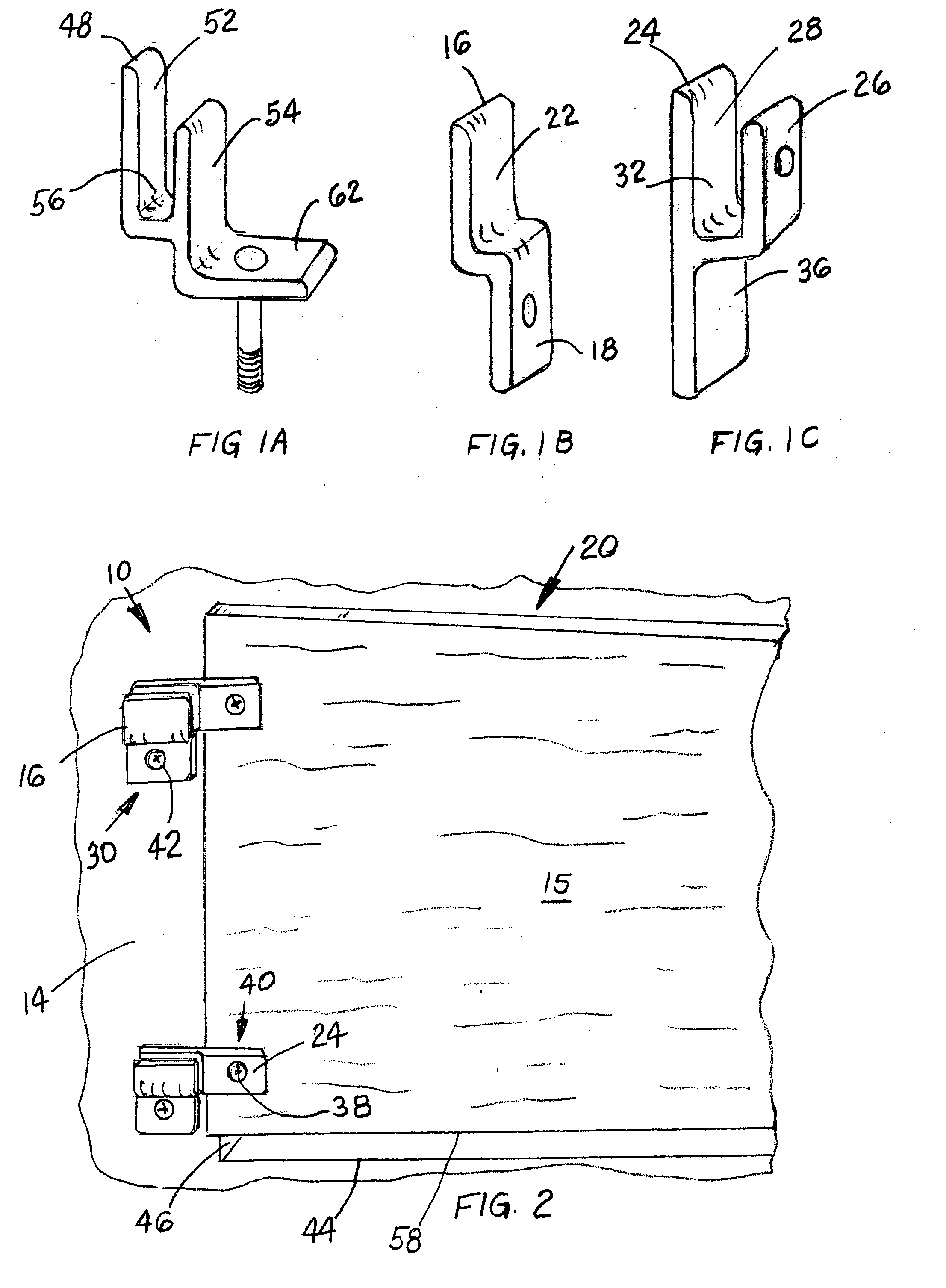
[0016]FIG. 1A is a perspective view of a double L-shaped bracket member used in conjunction with an interlocking bracket assembly of the present invention.

[0017]FIG. 1B is a perspective view of a Z-shaped bracket member used in conjunction with the interlocking bracket assembly of the present invention.

[0018]FIG. 1C is a perspective view of a Y-shaped bracket member used in conjunction with the interlocking bracket assembly of the present invention.

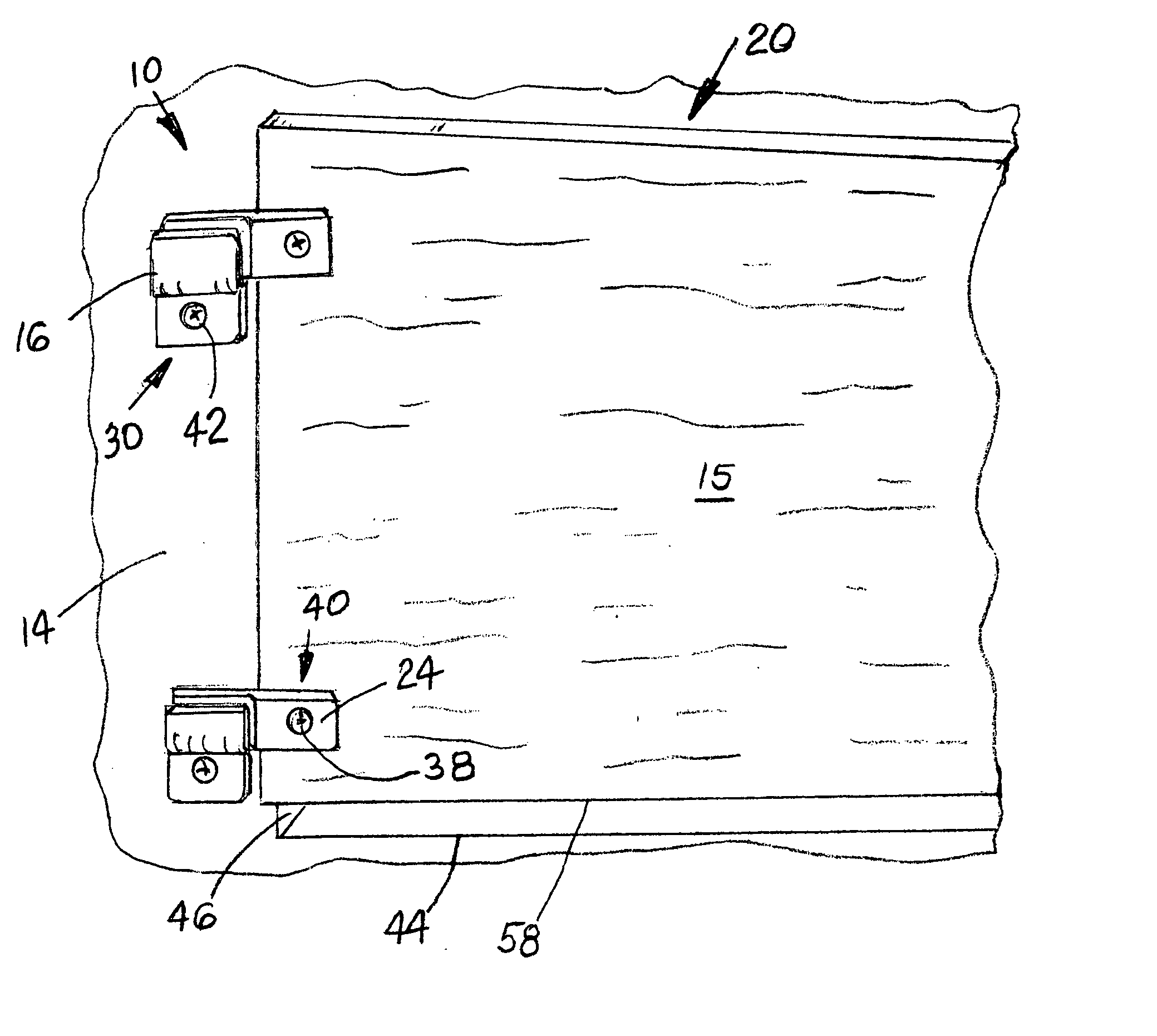
[0019]FIG. 2 is a plan view of the interlocking bracket assembly used to secure a protective covering over a window according to one embodiment.

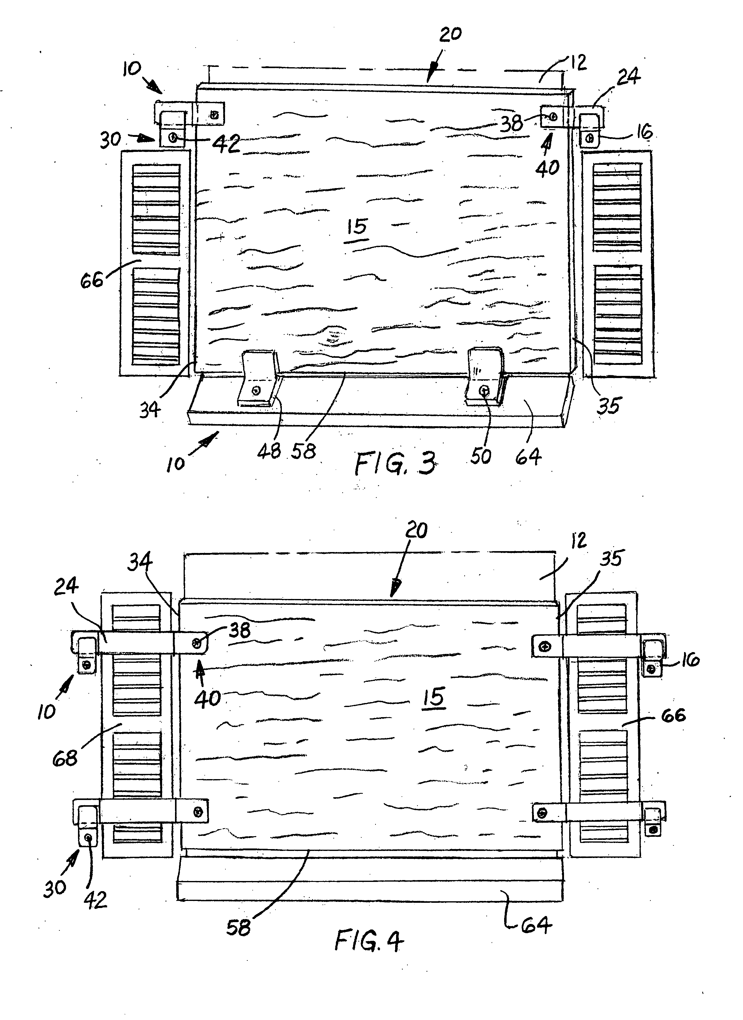
[0020]FIG. 3 is a plan view of the interlocking bracket assembly used to secure a protective covering over a window where shutters are mounted on either side of the window.

[0021]FIG. 4 is a plan view of the interlocking bracket assembly...


PUM


Abstract

An interlocking bracket assembly for removably securing a protective covering over a window in a structure during inclement weather conditions. The assembly includes at least two Z-shaped bracket members having a first portion offset a predetermined distance from a second portion thereof, and a first fastener for mounting the first portion of each of the Z-shaped bracket members to such structure on opposite sides of such window. Also included are at least two Y-shaped bracket members having a first portion, a substantially parallel spaced second portion and a third portion. A second fastener mounts opposing sidewall portions of such covering between the first and second portions of each of the Y-shaped bracket members. The third portion of each of such Y-shaped bracket members is slidably inserted between a corresponding second portion of each of the Z-shaped bracket members and such structure for removably securing such covering over such window.

Description

CROSS REFERENCE TO RELATED APPLICATIONS [0001] This application is closely related to and claims priority from U.S. Provisional Patent Application Ser. No. 60 / 808,352 filed on May 25, 2006 and U.S. Provisional Patent Application Ser. No. 60 / 816,026 filed on Jun. 23, 2006.FIELD OF THE INVENTION [0002] The present invention relates, in general, to protective coverings that are mounted over windows in a structure to shield them from high winds and debris during inclement weather conditions such as a hurricane and, more particularly, the invention relates to a reinforced, transparent protective cover assembly that shields a window from high winds and debris during a hurricane and, still more particularly, the invention relates to an interlocking bracket assembly that mounts a protective covering over a window without requiring such protective covering to be directly secured to the structure around such window. BACKGROUND OF THE INVENTION [0003] Protective coverings fastened over windows...

Claims


Application Information

Patent Timeline
IPC IPC(8): A47F5/00
CPCE06B9/02
Inventor SPIVEY, CURTIS
Owner SPIVEY CURTIS
Why Eureka
Try Eureka