Bonding and grounding clamp/connector for electrode conductors

a technology of bonding and grounding, applied in the direction of clamping/spring connection, electrical connection, connection, etc., can solve the problems of limited and expensive commercial products which are capable of achieving the desired mounted connection, and components which are expensive to manufacture, so as to achieve quick and easy secure affixed

Active Publication Date: 2011-04-19
BRIDGEPORT FITTINGS LLC
View PDF3 Cites 11 Cited by
  • Summary
  • Abstract
  • Description
  • Claims
  • Application Information

AI Technical Summary

Benefits of technology

[0012]By employing the present invention, all of the difficulties and drawbacks of prior art systems have been eliminated and an efficient, easily manufactured and easily assembled bonding and grounding clamp / connector is realized. In accordance with the present invention, a single housing is constructed incorporating a central passageway or channel formed therein which is constructed for receiving and retaining a typical grounding rod / grounding electrode conductor. In addition, the housing is constructed for being quickly and easily mounted and secured in a knockout hole formed in any desired electrical outlet box, junction box, meter box, or similar enclosure. In this way, the clamp / conductor of the present invention is quickly and easily installed and secured in any desired location in any required electrical box.
[0013]Furthermore, the housing of the clamp / connector of the present invention incorporates a locking screw threadedly mounted to the housing and positioned for quickly and easily securely affixing the grounding rod / grounding electrode conductor in the channel or passageway of the housing once positioned therein. As a result, the entire installation of the clamp / connector of the present invention is achieved by longitudinally advancing any desired grounding rod / grounding electrode conductor through the channel or passageway of the housing of the clamp / connector, and then securing the grounding rod / grounding electrode conductor to the clamp / connector by threadedly advancing the locking screw into secure engagement with the grounding rod / grounding electrode conductor. Finally, the entire clamp / connector is inserted through a knockout hole formed in the desired electrical box and then securely mounted in the desired position.
[0015]In this way, the clamp / connector of the present invention is quickly and easily securely affixed to any desired junction box, meter box, outlet box, electrical box, and the like, by telescopicly advancing the housing through a knockout hole formed in the particular box until the enlarged flange contacts the surface of the box, typically an inside surface. Then, the locking ring is advanced onto the housing in threaded engagement with the threaded zone of the housing of the clamp / connector, with the locking ring being threadedly advanced until secure affixation of the clamp / connector with the box is achieved.

Problems solved by technology

Although the requirement for properly securing a grounding rod or grounding electrode conductor to the power distributing outlet box, junction box, meter box, or other similar enclosure, in which the grounding rod / grounding electrode conductor is interconnected to the power carrying wires, commercially available products which are capable of achieving the desired mounted connection are both limited and expensive.
Typically, these prior art products incorporate components which are expensive to manufacture due to tolerance requirements for enabling these components to peripherally surround and secure the grounding rod / grounding electrode conductor to the housing of the clamp or connector.

Method used


Image

  • Bonding and grounding clamp/connector for electrode conductors
  • Bonding and grounding clamp/connector for electrode conductors
  • Bonding and grounding clamp/connector for electrode conductors

Examples


Embodiment Construction

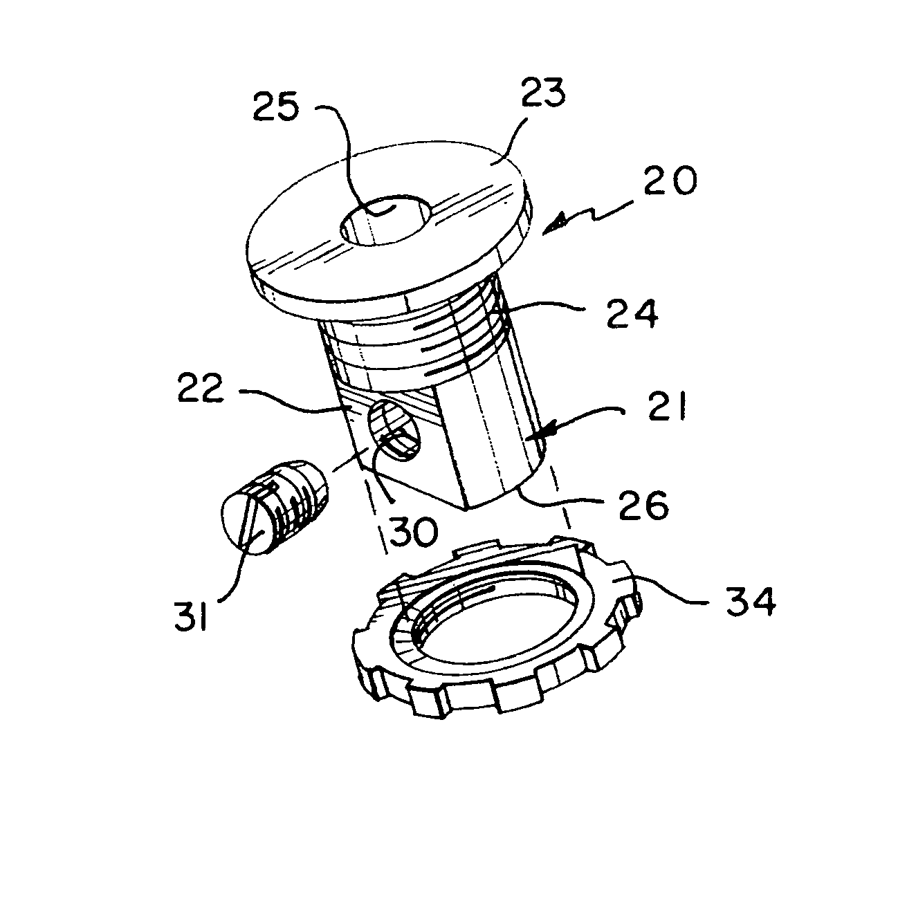
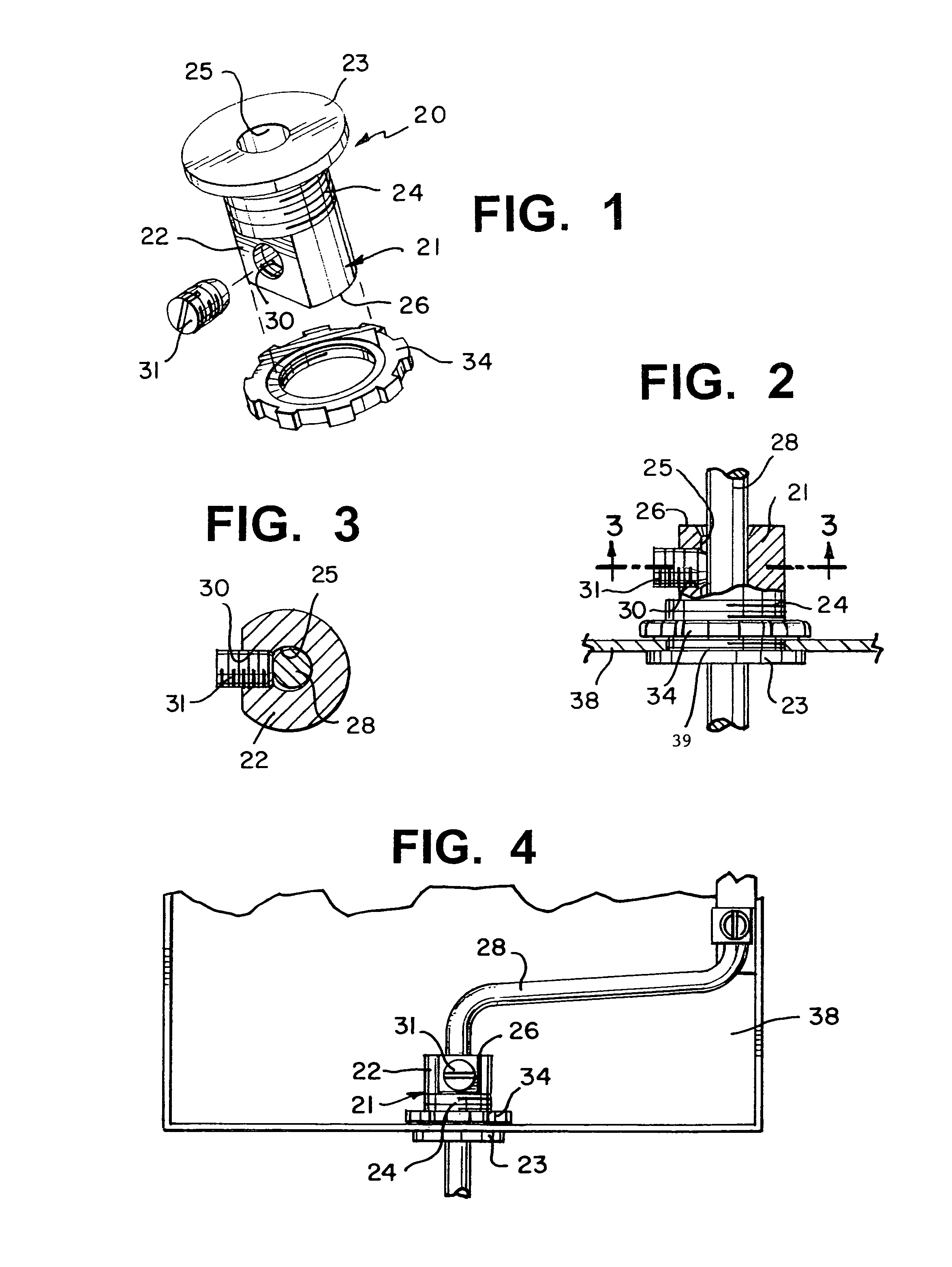
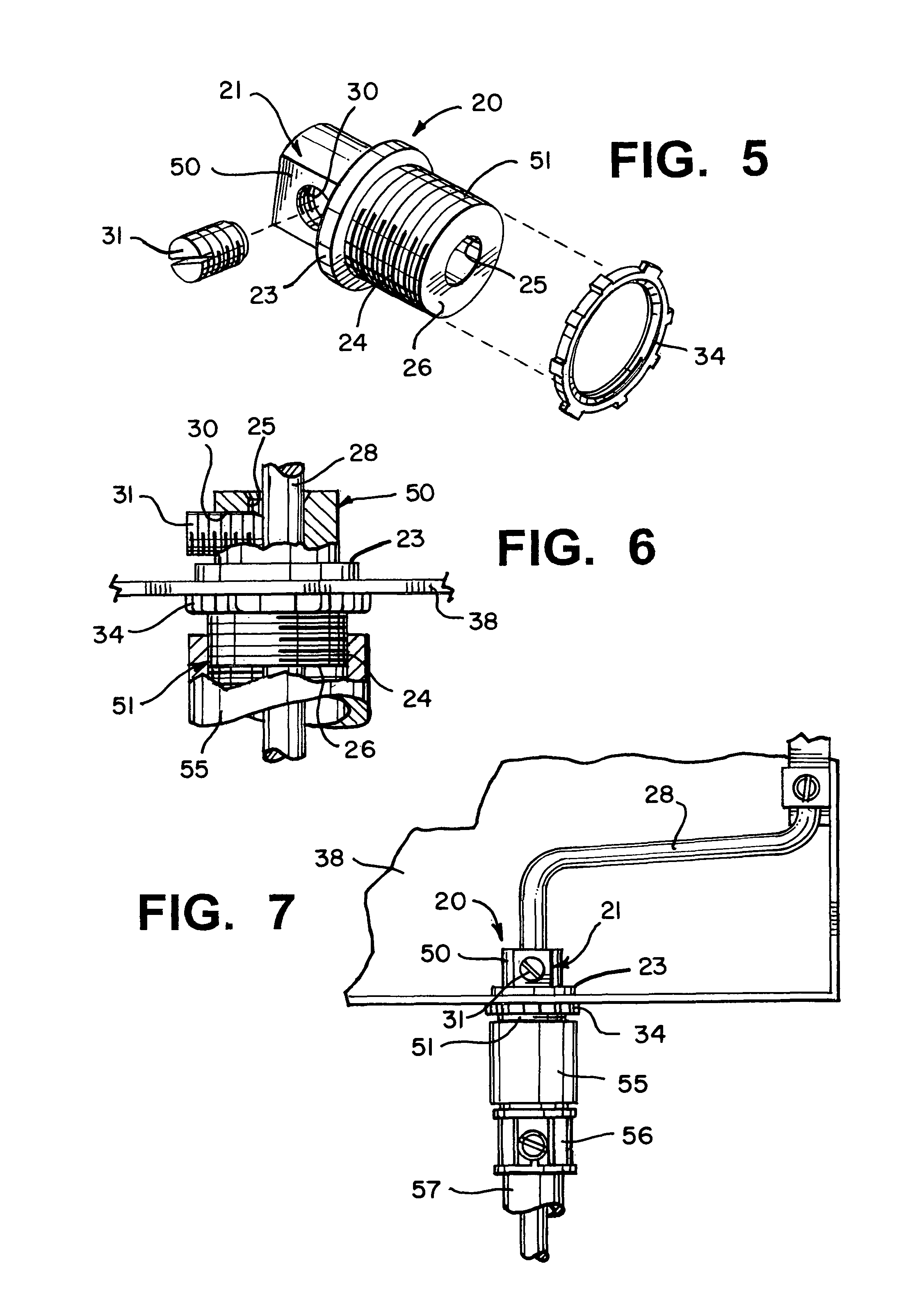
[0026]By referring to FIGS. 1-7, along with the following detailed disclosure, the construction and operation of two preferred alternate embodiments of the bonding and grounding clamp / connector of the present invention can best be understood. Although the following disclosure fully details each of the two alternate embodiments and presents the best mode for implementing the present invention, the bonding and grounding clamp / connector of the present invention can be constructed in further alternate configurations. Consequently, it is to be understood that the embodiments detailed herein are provided for exemplary purposes only and are not intended as a limitation of the present invention.

[0027]By referring to FIGS. 1-4, along with the following detailed disclosure, the construction and operation of one preferred embodiment of bonding and grounding clamp / connector 20 of the present invention can best be understood. As clearly depicted in these figures, bonding / grounding clamp / connecto...


PUM


Abstract

By providing a single housing incorporating a central passageway or channel formed therein which is constructed for receiving and retaining a typical grounding rod / grounding electrode conductor and constructing the housing for being quickly and easily mounted and secured in a knockout hole formed in any desired electrical outlet box, junction box, meter box, or similar enclosure, an efficient, easily manufactured and easily assembled bonding and grounding clamp / connector is realized. Preferably, the housing of the clamp / connector of the present invention incorporates a locking screw threadedly mounted to the housing and positioned for quickly and easily securely affixing the grounding rod / grounding electrode conductor in the channel or passageway of the housing once positioned therein.

Description

CROSS REFERENCE TO RELATED APPLICATIONS[0001]This application is a continuation of co-pending application Ser. No. 12 / 655,376 filed on Dec. 30, 2009 and is claiming domestic priority under all applicable sections of 35 U.S.C. §120.TECHNICAL FIELD[0002]This invention relates to electrical connectors, and more particularly, to electrical clamps or connectors constructed for bonding and securing grounding electrode conductors to the housing of an electrical service box, meter box, or other electrical enclosure.BACKGROUND OF THE INVENTION[0003]In the field of wiring homes and buildings, whether for new construction or for improvements or expansion, substantial development and product improvements have been made. Typically, these improvements are directed to enabling installers to securely and safely mount any desired wiring to any desired location in the most efficient and quickest manner.[0004]In any particular installation or location, various conduits or cables must be interconnected...

Claims


Application Information

Patent Timeline
Patent Type & Authority Patents(United States)
IPC IPC(8): H01R4/36
CPCH01R4/646H01R4/36
Inventor KIELY, KENNETH M.
Owner BRIDGEPORT FITTINGS LLC
Why Eureka
Try Eureka