Visual means of an endoscope

a technology of endoscope and endoscope, which is applied in the field of endoscope visual means, can solve the problems of high error rate in finding polypi and tumors

Active Publication Date: 2010-04-20
INVENDO MEDICAL GMBH
View PDF20 Cites 65 Cited by
  • Summary
  • Abstract
  • Description
  • Claims
  • Application Information

AI Technical Summary

Problems solved by technology

Especially in the field of endoscopy, it has turned out that, for instance, when exploring the intestines the error rate in finding polypi and tumors is still very high.
The difficulty consists in the fact that the field of vision of an inserted endoscope is and also has to be directed substantially ahead so as to be capable of visually monitoring and controlling the inserting movement.

Method used


Image

  • Visual means of an endoscope
  • Visual means of an endoscope
  • Visual means of an endoscope

Examples


Embodiment Construction

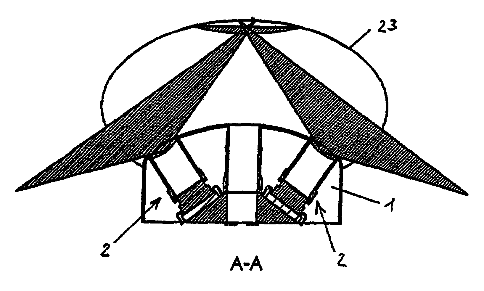
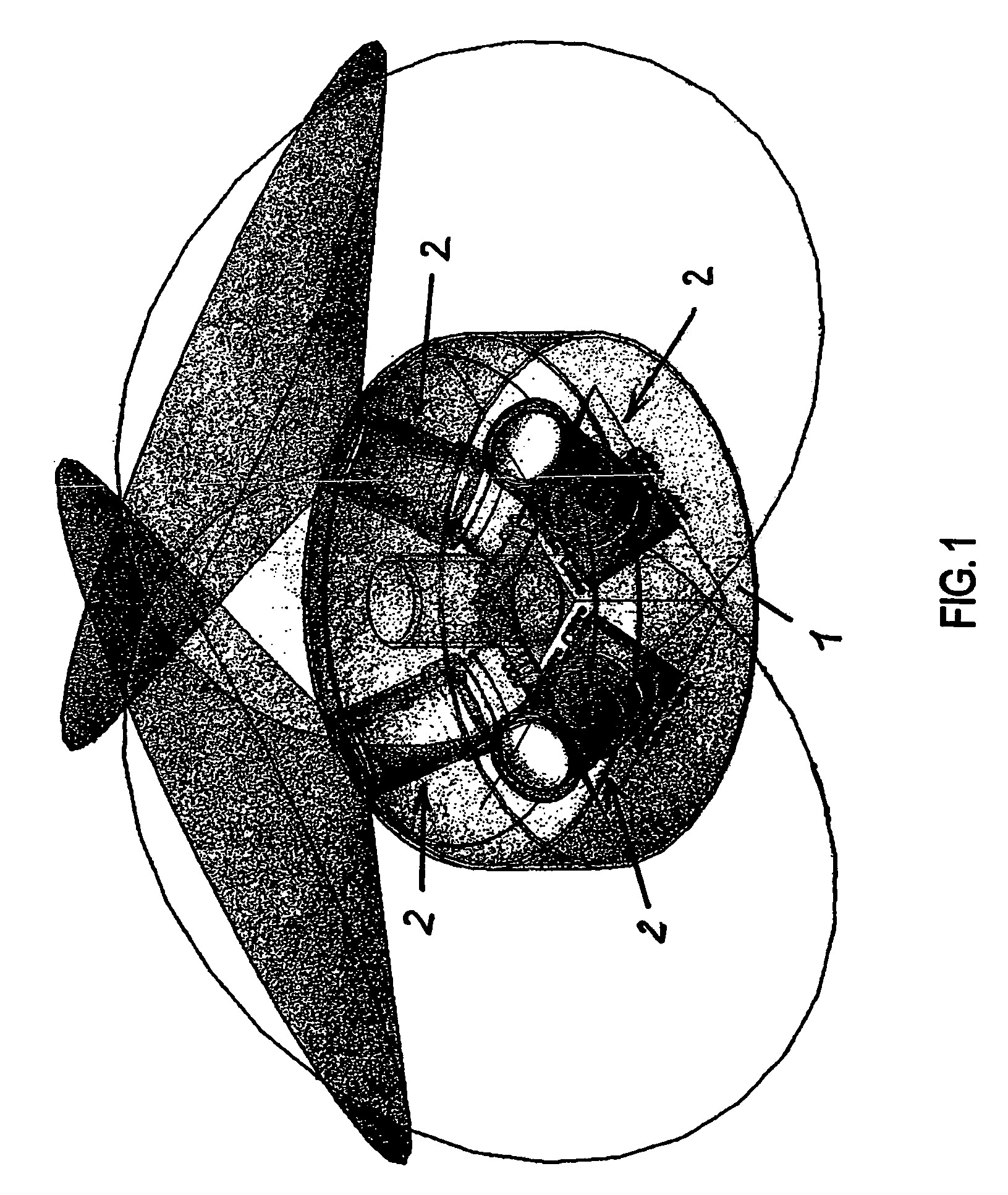
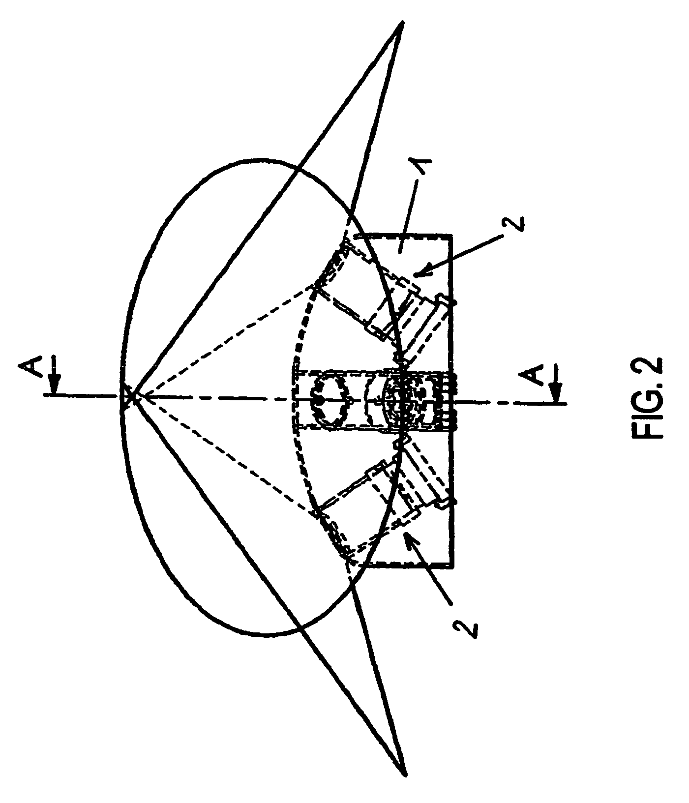
[0023]First of all, it is pointed out that in the present embodiment the endoscope is constructed of an endoscope shaft (not shown) and an endoscope head 1 arranged at the same, wherein a front area thereof is illustrated in FIG. 1. As an alternative, it is, however, also possible to design the endoscope in the form of a probe or a capsule (without a shaft protruding from the body cavity) in which the visual means according to the invention is preferably accommodated in a front area of the capsule.

[0024]As one can clearly take from FIGS. 1-4, the visual means according to the invention in the present case consists of four optical systems 2 each of which comprises a lens unit 3-6 and a photosensitive element 7 or microchip arranged beneath the lens unit. Alternatively, however, only two or three optical systems 2 of this type can be arranged. As a further alternative, each of the represented optical systems could be replaced with a plurality of smaller optical systems which are coupl...


PUM


Abstract

A visual means of an endoscope comprising at least one optical system or composite optical system arranged at a front area of the endoscope. The at least one optical system or the at least one composite optical system realizes an aperture angle of more than 180° and is arranged such that the field of vision thereof reaches both beyond the normal to the direction of movement and beyond the longitudinal axis of the endoscope pointing ahead.

Description

BACKGROUND OF INVENTION[0001]1. Field of the Invention[0002]The present invention relates to a visual means of an endoscope.[0003]2. Discussion of the Prior Art[0004]In principle, endoscopes, also in the form of capsules or probes, wherein the latter basically represent endoscopes having no endoscope shaft, are equipped with visual or rather optical systems for exploring body cavities such as the intestines, the stomach, blood vessels, etc., the visual or rather optical systems permitting a visual inspection or image recording of parts of the body cavity on the basis of which diagnoses of diseases can be made. In DE 101 16 056 A1, for instance, a generic endoscopic visualizing device comprising different image systems is known. Concretely spoken, the known visualizing device includes two image systems having different visual angles and different optical parameters (for instance different aperture angles) whose fields of vision directed ahead are partly overlapping and thus permit tw...

Claims


Application Information

Patent Timeline
Patent Type & Authority Patents(United States)
IPC IPC(8): A61B1/04A61B1/00G02B3/12G02B23/24G02B23/26
CPCG02B23/243
Inventor PAUKER, FRITZVIEHBACH, THOMASBOB, KONSTANTIN
Owner INVENDO MEDICAL GMBH
Why Eureka
Try Eureka