Wide-band slot antenna apparatus with stop band

a technology of antenna apparatus and stop band, applied in the direction of slot antenna, antenna, basic electric elements, etc., can solve the problems of not being able to implement ultra-wideband filters, and cannot achieve the currently required ultra-wideband characteristics, etc., to achieve the effect of suppressing radiation characteristics, avoiding interference with other communication systems, and efficiently covering desired communication areas

Active Publication Date: 2010-04-20
PANASONIC INTELLECTUAL PROPERTY CORP OF AMERICA
View PDF8 Cites 7 Cited by
  • Summary
  • Abstract
  • Description
  • Claims
  • Application Information

AI Technical Summary

Benefits of technology

[0028]As described above, the unbalanced-feed wideband slot antenna apparatus of the present invention not only can achieve a wideband operation which is difficult for prior art slot antenna apparatuses to achieve, but also can maintain a main beam direction across an operating band, and implement a band-stop function to suppress radiation characteristics in a partial band, thus helping to implement a power-saving and high-speed UWB communication system that avoids interference with other communication systems, while efficiently covering desired communication areas.

Problems solved by technology

On the other hand, in cases of a patch antenna and a one-half effective wavelength slot antenna which are known as basic antennas, the operating bands converted to fractional bandwidths are less than 5% and less than 10%, respectively, and thus, such antennas cannot achieve a wideband property such as that of UWB.
However, according to the frequency characteristics shown in Patent Document 1, it is not enough to obtain a currently required ultra-wideband characteristics.
Particularly, in Europe and Japan, it is unauthorized by regulation to output UWB signals in the 5 GHz band used for wireless LANs, and thus, it is necessary to deal with this regulation.
On the other hand, since it is difficult to implement a ultra-wideband filter for a GHz band with small size, a band-stop function is required to be provided for an antenna itself.
As discussed above, sufficient wide band operation has not been achieved in the prior art slot antennas.
Although the printed monopole antenna, which is expected as a wideband antenna for UWB, can operate with low reflection in an ultra-wideband and also achieves the band-stop function in parts of the band, it is difficult to maintain the main beam direction in an operating band.
As a result, even when such an antenna is applied to a UWB system, it is difficult to cover a communication area.
Further, according to the examples disclosed in FIGS. 13 and 19 of Patent Document 1, it is difficult to achieve a characteristic of input impedance matching with low reflection in an ultra-wideband.
Further, as compared to the antennas of the first and second prior art examples with one-end-open slot resonators which are of one-quarter effective wavelength resonators, it is disadvantageous in reducing size to use a slot resonator which is short-circuited at both ends and is of a one-half effective wavelength resonator.
Thus, it is extremely difficult to stably establish communication conditions over the entire band.

Method used


Image

  • Wide-band slot antenna apparatus with stop band
  • Wide-band slot antenna apparatus with stop band
  • Wide-band slot antenna apparatus with stop band

Examples


first preferred embodiment

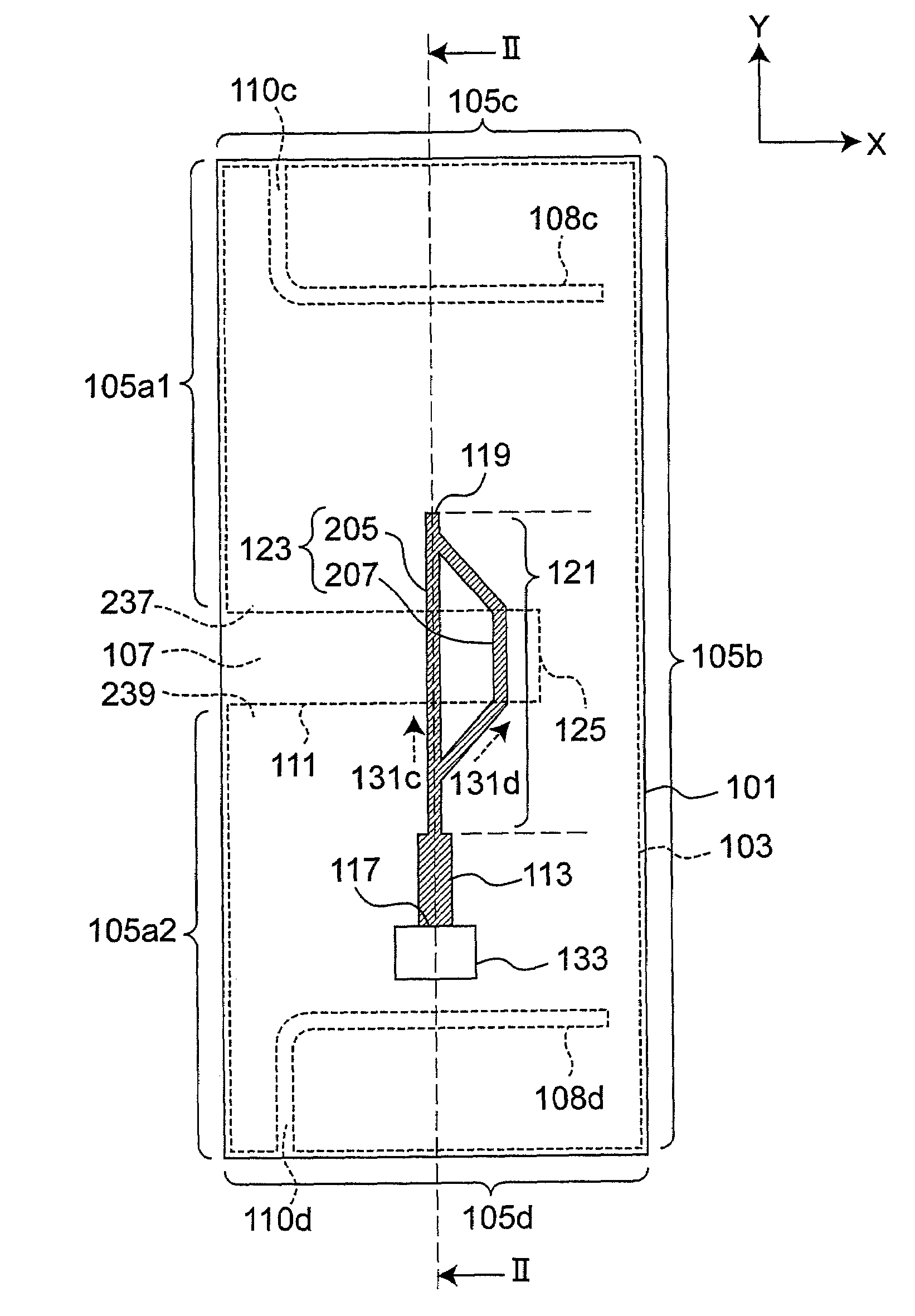
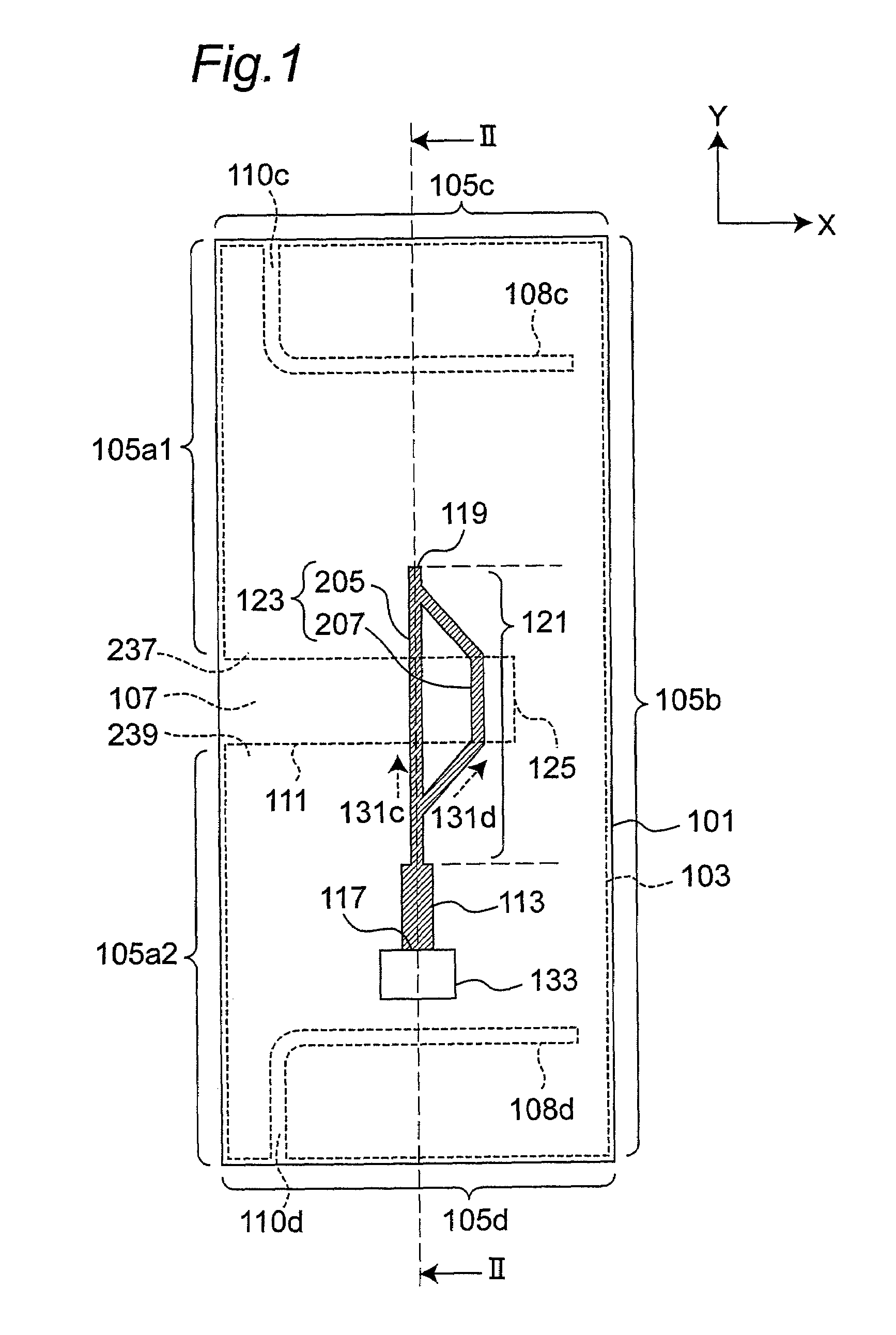
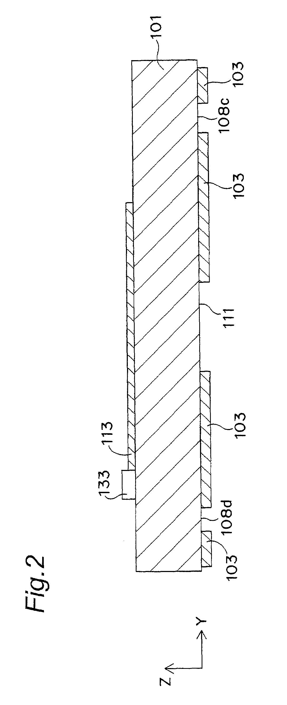
[0069]FIG. 1 is a schematic top view showing a structure of an unbalanced-feed wideband slot antenna apparatus according to a first preferred embodiment of the present invention. FIG. 2 is a schematic cross-sectional view along the dashed line in FIG. 1. In schematic top views of FIG. 1 and others, the structure of a backside of a substrate 101 is shown by phantom (i.e., by dotted lines). For the purpose of explanation, refer to XYZ coordinates as shown in the respective drawings.

[0070]The unbalanced-feed wideband slot antenna apparatus according to the preferred embodiment of the present invention is characterized by including: a grounding conductor 103 with an outer edge including a first portion facing a radiation direction (i.e., a −X direction) and a second portion other than the first portion; a one-end-open slot 111 formed in the grounding conductor 103 along the radiation direction such that an open end 107 is provided at the center of the first portion of the outer edge of ...

second preferred embodiment

[0110]FIG. 15 is a schematic top view showing a structure of an unbalanced-feed wideband slot antenna apparatus according to a second preferred embodiment of the present invention. The unbalanced-feed wideband slot antenna apparatus according to the present preferred embodiment is characterized by having a different feed structure than that in the first preferred embodiment. As shown in FIG. 15, a grounding conductor 103 is configured to be symmetric about a symmetry axis in an X-axis direction passing through a slot 111, and then, an unbalanced feed line 113 is connected to an antenna feeding point 117 provided on the symmetry axis of the grounding conductor 103 at the +X side of the grounding conductor 103. Thus, since the antenna feeding point 117 is provided on the symmetry axis of the grounding conductor 103, the antenna feeding point 117 has an input and output impedance higher than to an impedance in an unbalanced mode of the grounding conductor 103.

[0111]As shown in FIG. 15,...

implementation examples

[0115]In order to clarify the effects according to the preferred embodiments of the present invention, the impedance characteristics and radiation characteristics of slot antenna apparatuses of implementation examples of the present invention and slot antenna apparatuses of comparative examples were analyzed by a commercially available electromagnetic analysis simulator. Table 1 shows circuit board setting parameters common among first, second, and third implementation examples of the present invention. Table 2 shows circuit board setting parameters common between first and second comparative examples.

[0116]

TABLE 1Material of dielectric substrate 101FR4Thickness H of dielectric substrate 1010.5mmDepth D of dielectric substrate 10111.5mmWidth W of dielectric substrate 10132mmThickness t of wiring0.04mmSlot length Ls8.8mmSlow width Ws2.5mmLengths Wg1 and Wg2 of side portions 105a113.8mmand 105a2 on the −X sideWidth W1 of unbalanced feed line 1130.95mmWidth W2 of inductive region 1210....


PUM


Abstract

A slot antenna apparatus includes a grounding conductor having an outer edge including a first portion facing a radiation direction and a second portion other than the first portion, a one-end-open feed slot formed in the grounding conductor along the radiation direction such that an open end is provided at a center of the first portion, and a feed line including a strip conductor close to the grounding conductor and intersecting with the feed slot at at least a part thereof to feed a radio frequency signal to the feed slot. The slot antenna apparatus further comprises at least one one-end-open parasitic slot having an electrical length equivalent to one-quarter effective wavelength in a certain stop band, the parasitic slot having an open end at the second portion, and being formed in the grounding conductor so as not to intersect with the feed line.

Description

BACKGROUND OF THE INVENTION[0001]1. Field of the Invention[0002]The present invention relates to an antenna apparatus for transmitting and receiving analog radio frequency signals or digital signals in a microwave band, a millimeter-wave band, etc. More particularly, the present invention relates to a slot antenna apparatus operable in a wideband and having stop bands.[0003]2. Description of the Related Art[0004]A wireless device operable in a much wider band than that of prior art devices is required for the following two reasons. As the first reason, it is intended to implement a novel short-range wireless communication system with the authorization of use of a very wide frequency band, i.e., an ultra-wideband (UWB) wireless communication system. As the second reason, it is intended to utilize a variety of communication systems each using different frequencies, by means of one terminal.[0005]For example, when converting a frequency band into a fractional bandwidth being normalized...

Claims


Application Information

Patent Timeline
Patent Type & Authority Patents(United States)
IPC IPC(8): H01Q13/10H01Q5/00H01Q5/10H01Q5/25H01Q5/307H01Q5/35H01Q5/50H01Q7/00
CPCH01Q13/106H01Q5/50H01Q5/385
Inventor KANNO, HIROSHIFUJISHIMA, TOMOYASU
Owner PANASONIC INTELLECTUAL PROPERTY CORP OF AMERICA
Why Eureka
Try Eureka