Tubing retrievable injection valve

a safety valve and tubing technology, applied in the direction of fluid removal, borehole/well accessories, construction, etc., can solve the problem that the force is not sufficient to hold the flapper

Inactive Publication Date: 2010-04-27
BAKER HUGHES HLDG LLC
View PDF29 Cites 43 Cited by
  • Summary
  • Abstract
  • Description
  • Claims
  • Application Information

AI Technical Summary

Problems solved by technology

The strength of the force is not sufficient to hold the flapper open against a torsion spring on a pivot pin, when there is no flow through the valve.

Method used


Image

  • Tubing retrievable injection valve
  • Tubing retrievable injection valve
  • Tubing retrievable injection valve

Examples


Embodiment Construction

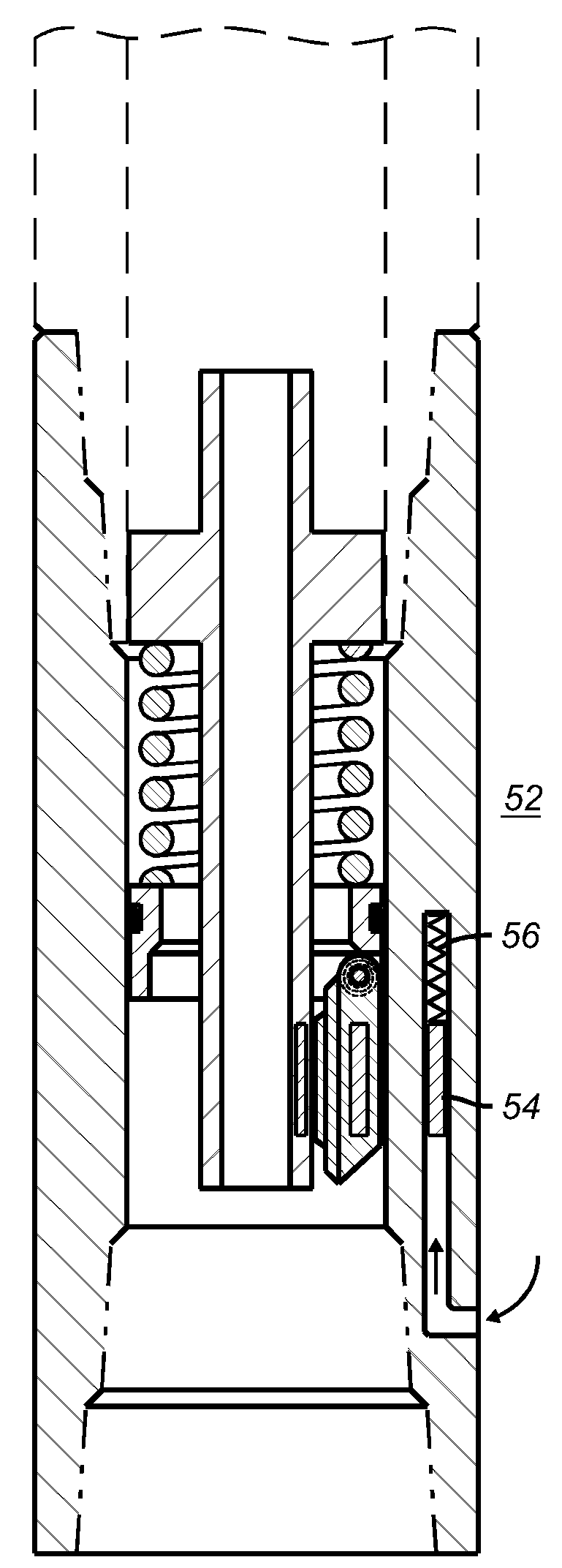
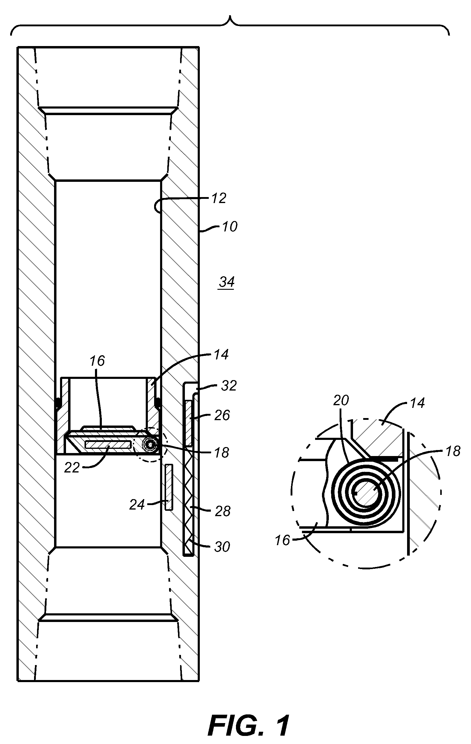
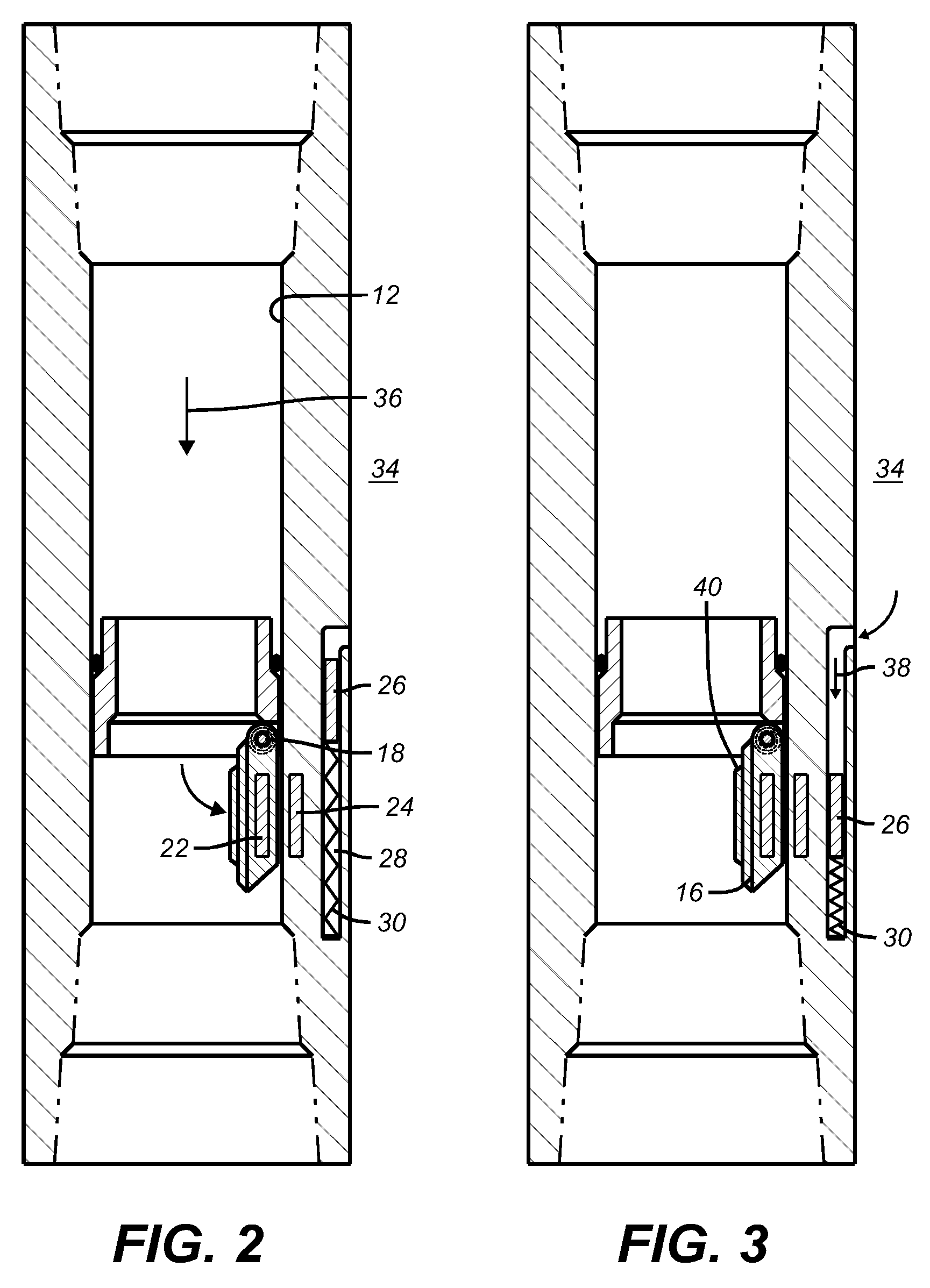
[0014]FIG. 1 illustrates a housing 10 having a passage 12 and a seat 14 mounted inside. A flapper 16 is pivotally mounted on a pin 18 around which is mounted a closure device schematically illustrated as a torsion spring 20. The flapper 16 has a magnet 22 that it supports or alternatively the flapper 16 can be made at least in part or totally of a magnetic material. In the preferred embodiment the magnet 22 is imbedded in the flapper 16. A magnet 24 is supported by housing 10 and in the preferred embodiment is outside the passage 12 in the wall of the housing 10. Housing 12 is preferably built of a non-magnetic material that can endure the service requirements of the application from the perspective of mechanical loads, pressures applied and exposure to well conditions. In the preferred embodiment the housing 10 is made of Inconel®. Also within the wall of the housing 10 is a magnet 26 in a recess 28 and biased by a spring 30. Recess 28 is open at 32 to the surrounding annulus 34. T...


PUM


Abstract

A flapper type downhole valve is opened by flow against the flapper. The flapper and the housing contain magnets that hold the flapper open after it has been opened by flow to keep the flapper from chattering from the flow going past it. The strength of the force is not sufficient to hold the flapper open against a torsion spring on a pivot pin, when there is no flow through the valve. The valve can still be held in the locked open position with no flow through the housing by pressurizing the surrounding annulus to position another magnet to increase the holding force to a level greater than the force of the torsion spring. The additional magnet is spring biased so that upon removal of annulus pressure it shifts to allow the flapper to close. Alternative designs with and without a flow tube are possible. Fixed or movable restrictions can be associated with the flow tube to create a force to shift it to open a flapper with flow into the well.

Description

FIELD OF THE INVENTION[0001]The field of the invention is downhole safety valves and more particularly valves that are used to control one way flow in injection well service.BACKGROUND OF THE INVENTION[0002]Safety valves have been used in wells to control them in emergency situations. They typically feature a disc known as a flapper that is biased against a seat above it by a torsion spring mounted on a pivot pin. In many designs a hydraulic system creates pressure at the surface that is transmitted through a control line to a piston in the housing of the valve. The piston is typically coupled to a flow tube for tandem movement. Typically the flow tube and operating piston combination is moved against the bias of a closure spring so that when hydraulic pressure is removed or lost in the control line, the closure spring can move the flow tube and piston back against any net force such as the net hydrostatic pressure in the control line. In some designs the hydrostatic forces in the c...

Claims


Application Information

Patent Timeline
Patent Type & Authority Patents(United States)
IPC IPC(8): E21B34/06
CPCE21B34/105E21B2034/005E21B2200/05
Inventor O'MALLEY, EDWARD J.RANJAN, PRIYESHMURRAY, DOUGLAS J.
Owner BAKER HUGHES HLDG LLC
Why Eureka
Try Eureka