
Manual disconnect system

a disconnect system and manual technology, applied in the direction of coupling device connection, coupling parts engagement/disengagement, emergency protective arrangements for limiting excess voltage/current, etc., can solve the problems of large installation footprint of the disconnect unit and drawbacks of the prior art manual disconnect uni

Active Publication Date: 2010-04-27
J S T CORP
View PDF3 Cites 14 Cited by
  • Summary
  • Abstract
  • Description
  • Claims
  • Application Information

AI Technical Summary

Benefits of technology

[0007]It is another object of the invention to provide a manual disconnect system that enables a user to remove the connector without using any tools.

Problems solved by technology

However, there are drawbacks in prior art manual disconnect units.
Also, the disconnect unit requires a large footprint for installation.

Method used


Image

  • Manual disconnect system
  • Manual disconnect system
  • Manual disconnect system

Examples


Embodiment Construction

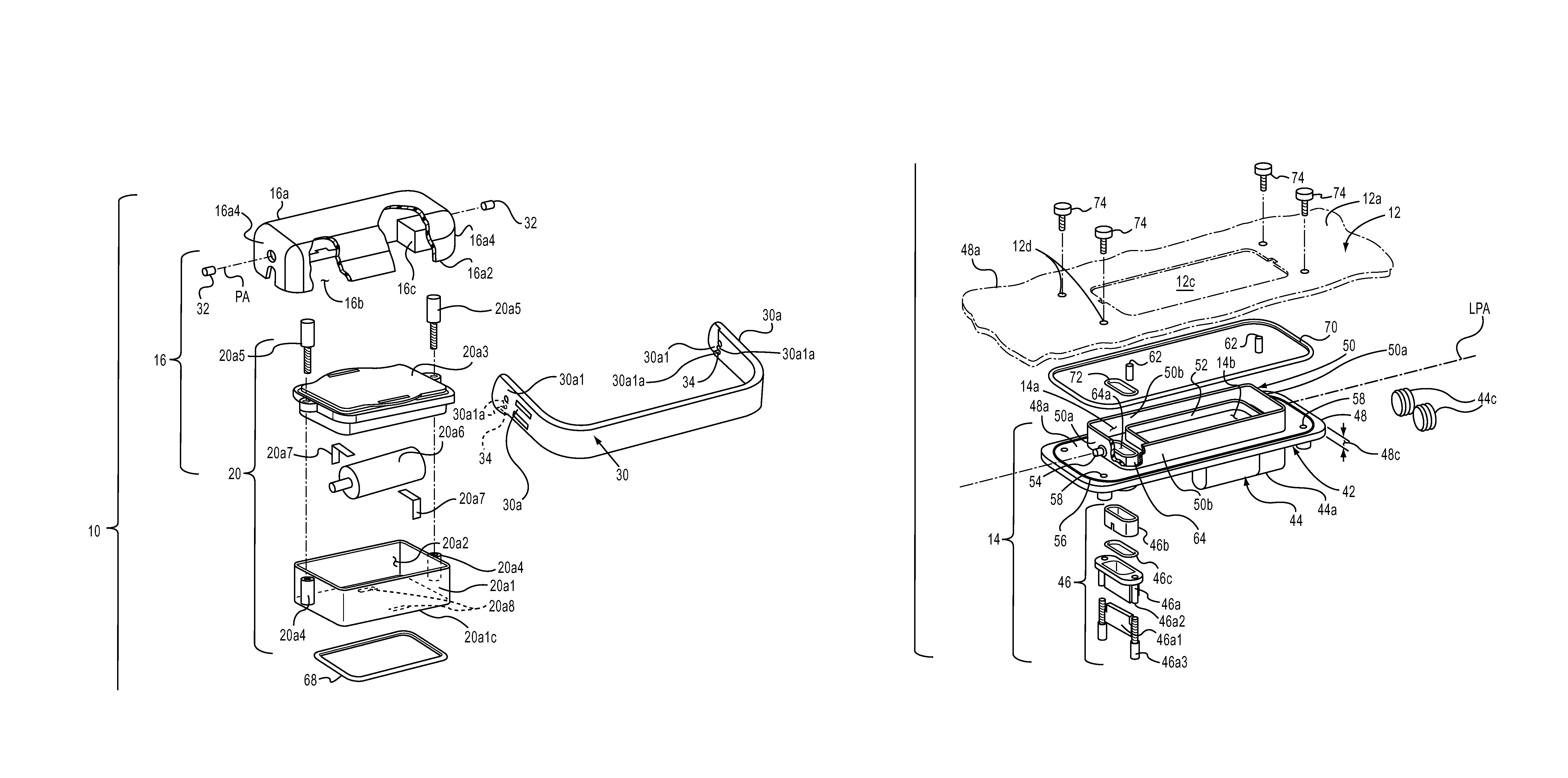
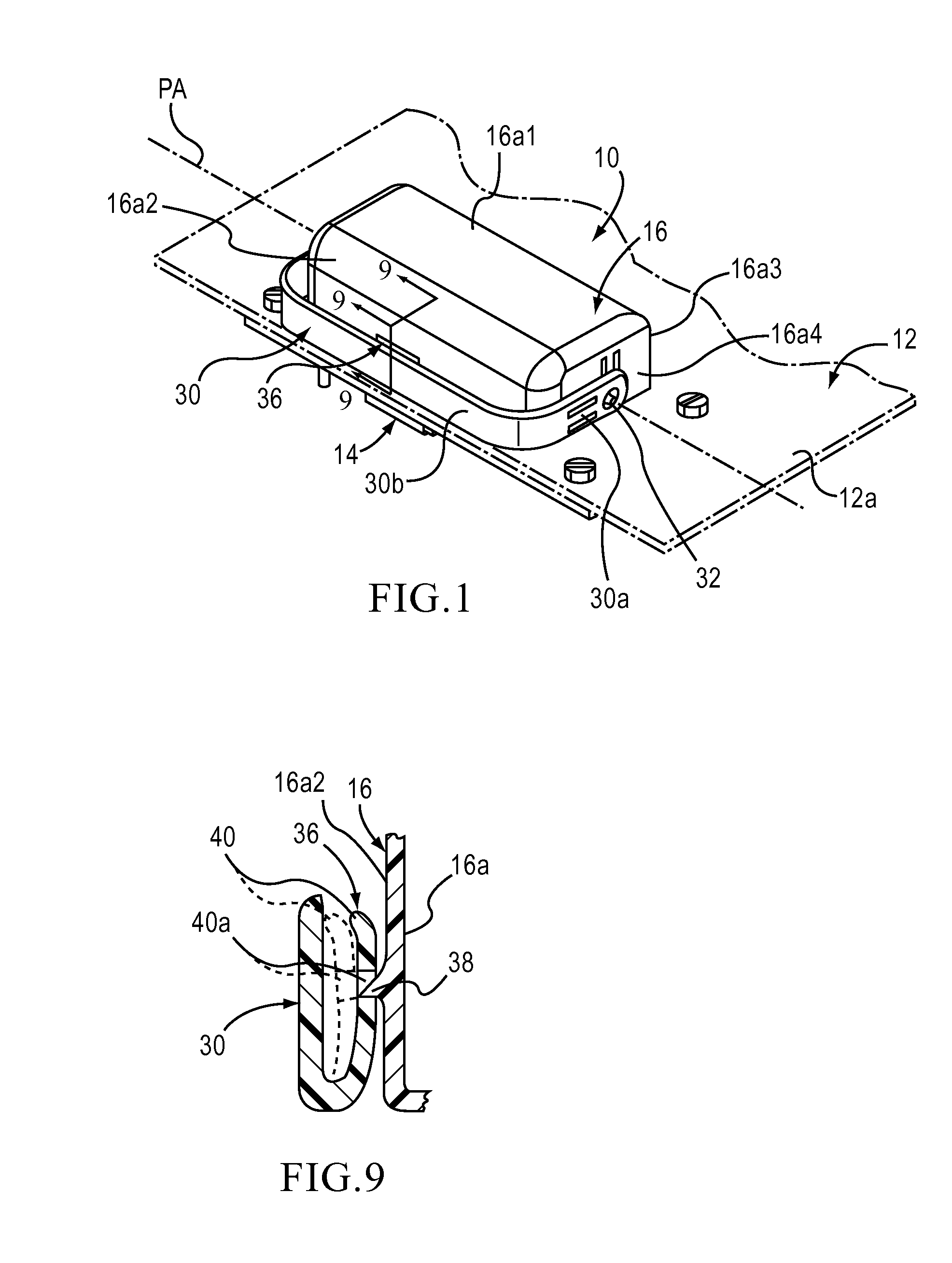
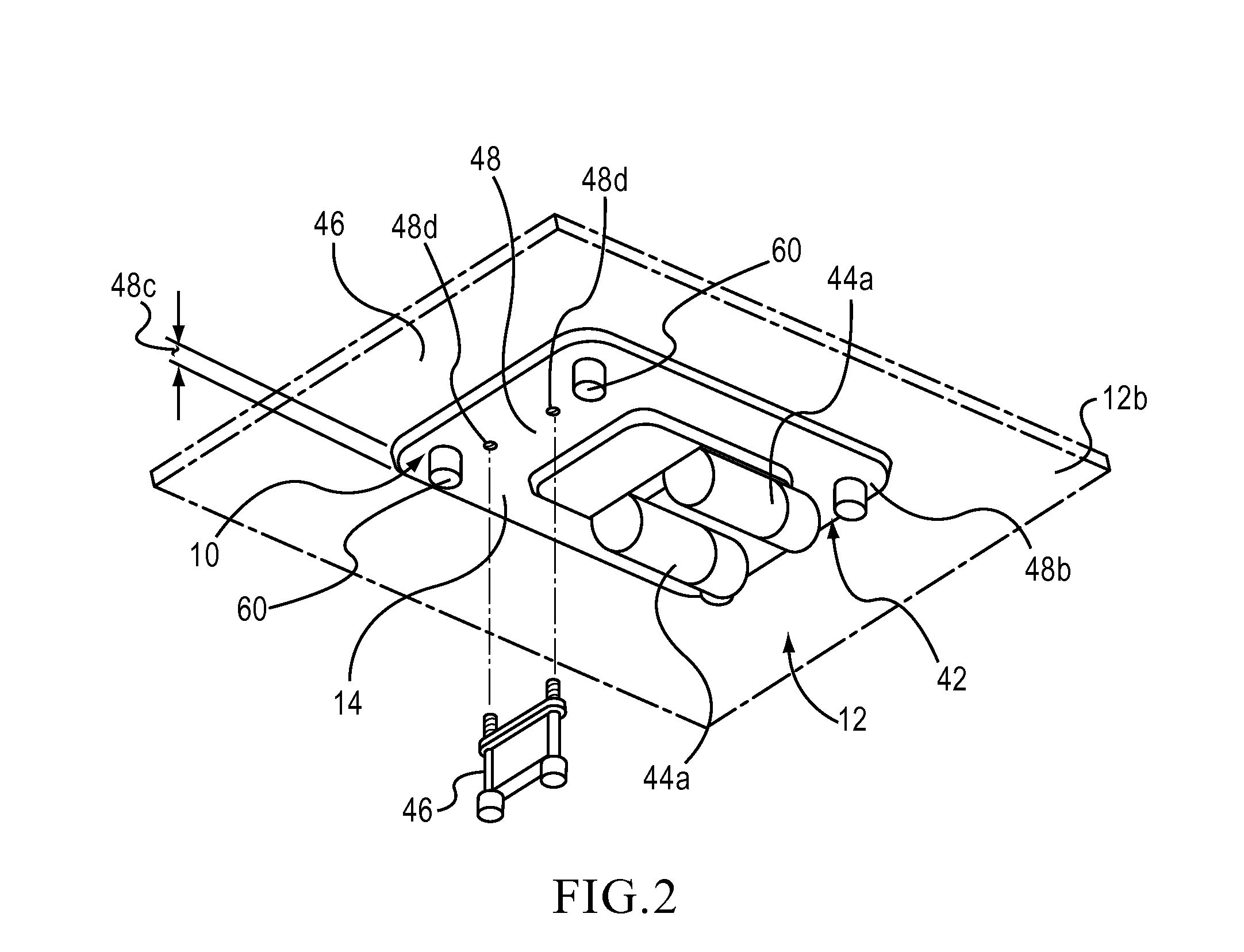
[0030]Hereinafter, embodiments of the present invention will be described with reference to the attached drawings. The structural components common to those of the prior art and the structural components common to respective embodiments of the present invention will be represented by the same symbols and repeated description thereof will be omitted.

[0031]Also, throughout the detailed description of the exemplary embodiments, more descriptive terms such as “above”, “top”, “front”, “bottom” and the like are used in reference to the drawing figures and shall not be construed to limit the scope of the invention. These terms are considered to be more descriptive of the invention particularly as the orientation of the embodiments of the invention is shown the drawing figures. It is believed that the detailed description of the exemplary embodiments is easier for a reader to comprehend using the more descriptive terms rather than non-descriptive terms. However, one of ordinary skill in the...


PUM


Abstract

A manual disconnect system includes a battery part, a disconnect part, a circuit assembly and a fuse assembly with a fuse connector and a circuit connector connected to the battery part. The battery part has a main compartment and a fuse assembly subcompartment. The disconnect part is releasably connected to the battery part. The fuse assembly is releasably received by the fuse assembly subcompartment. When the disconnect part is connected to the battery part, the fuse assembly and the fuse connector are electrically connected together and the circuit assembly and the circuit connector are electrically connected together. Upon detaching the disconnect part and the battery part from each other, the circuit assembly and the circuit connector are electrically disconnected from one another while the fuse assembly remains releasably connected to the battery part in the fuse assembly subcompartment and electrically connected to the fuse connector.

Description

FIELD OF THE INVENTION[0001]The present invention relates to a manual disconnect system. More particularly, the present invention is directed to a manual disconnect system that, if desired, can be sealed.BACKGROUND OF THE INVENTION[0002]Manual disconnect units that facilitate electrical disconnection, particularly from high current connections, are known in the art. One such manual disconnect unit is disclosed in U.S. Pat. No. 6,773,307. This high current disconnect unit includes a fuse, a current limiting resistor, a manual disconnection device and a pair of connection elements for connecting the high current disconnect system to an electrical circuit. The manual disconnect unit is wired in series with the fuse and provides a user selectable circuit interrupt. The current limiting resistor is wired in parallel with the manual disconnection unit and in series with the fuse. The manual disconnection unit is wired in series with the fuse and provides a user selectable circuit.[0003]Ho...

Claims


Application Information

Patent Timeline
Patent Type & Authority Patents(United States)
IPC IPC(8): H01R13/66
CPCH01H9/085H01H9/104H01R13/66H01R13/633H01R13/6335H01H2009/108
Inventor HONG, KIN BOONCHUANG, LEE YIN
Owner J S T CORP
Learn More