[0007]The fuse device in accordance with the invention has an electrically insulating substrate with an upper surface, a thick film fusible conductor applied to the surface of the substrate and a cover layer of an electrically insulating material of good
thermal conductivity applied directly to the thick film fusible conductor and adjoining regions of the surface of the substrate. It is possible with this arrangement to improve the resistance of the fuse device to very briefly flowing high currents in a manner which is simple to manufacture (namely a simple structure with few
layers). The cover layer has a number of complementary effects: it stabilises the surface of the fusible conductor, it acts as a brief thermal buffer (or thermal drain and store) and it can inhibit the production and maintenance of an arc during and after
tripping.
[0012]This small substrate size for thick film fuse devices permits a relatively large width (preferably in conjunction with a relatively large
layer thickness), a relatively large cross-sectional area of the fusible conductor and thus a
high current capacity, which (and also the cover layer in accordance with the invention) inhibits rupturing under brief current pulses of
high amplitude.
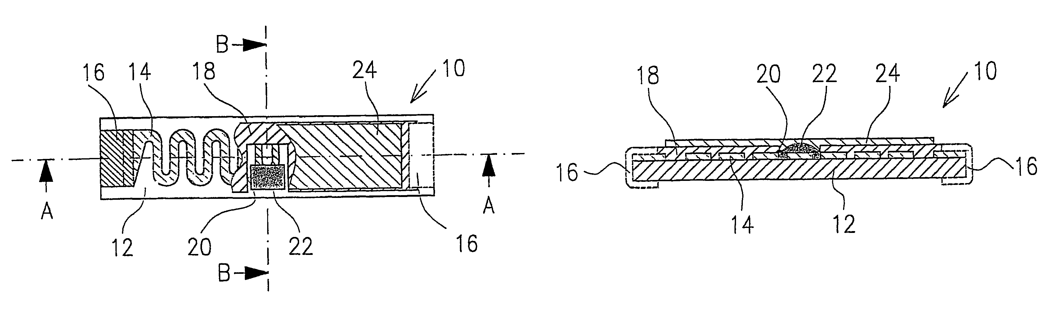
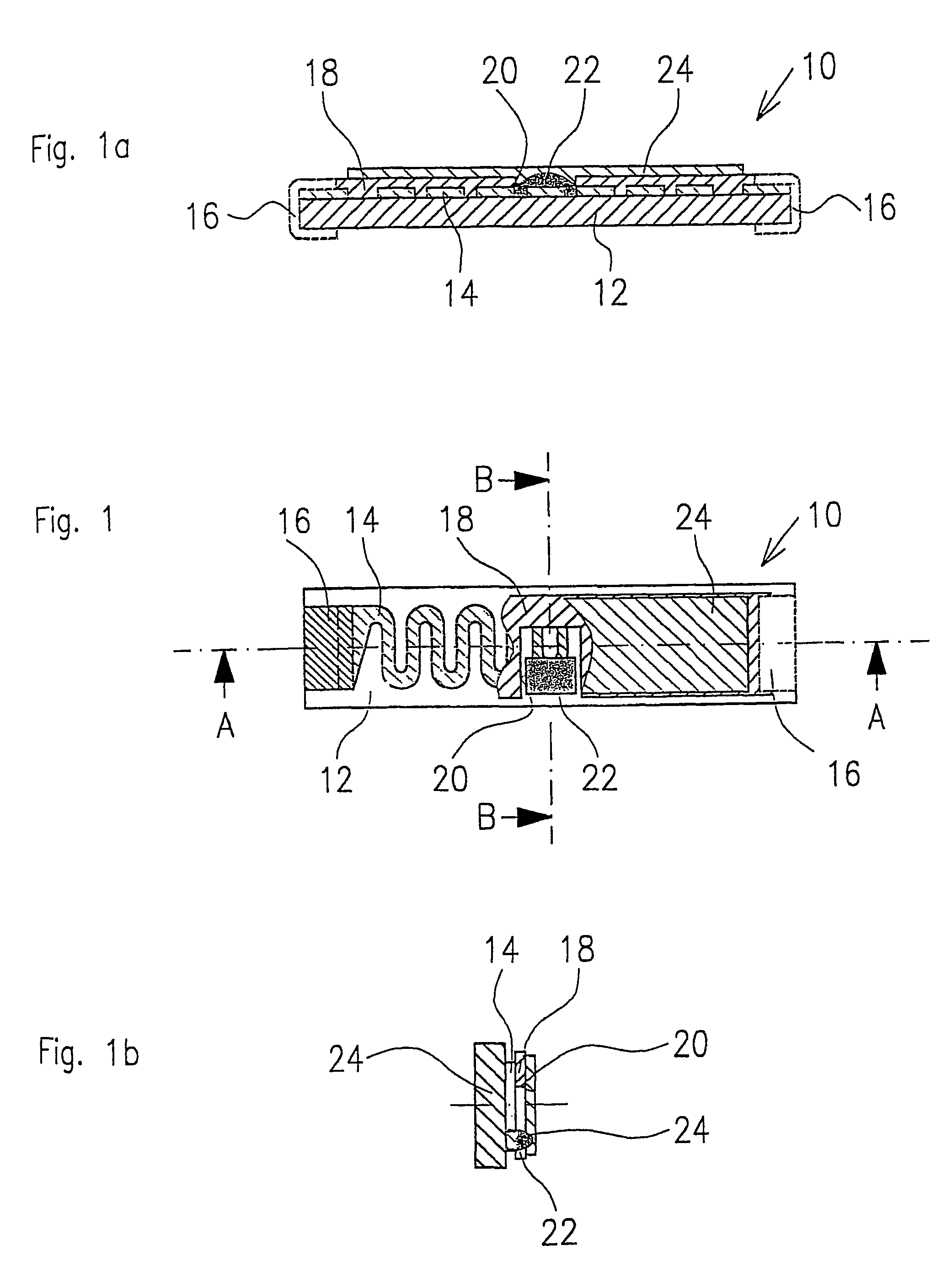
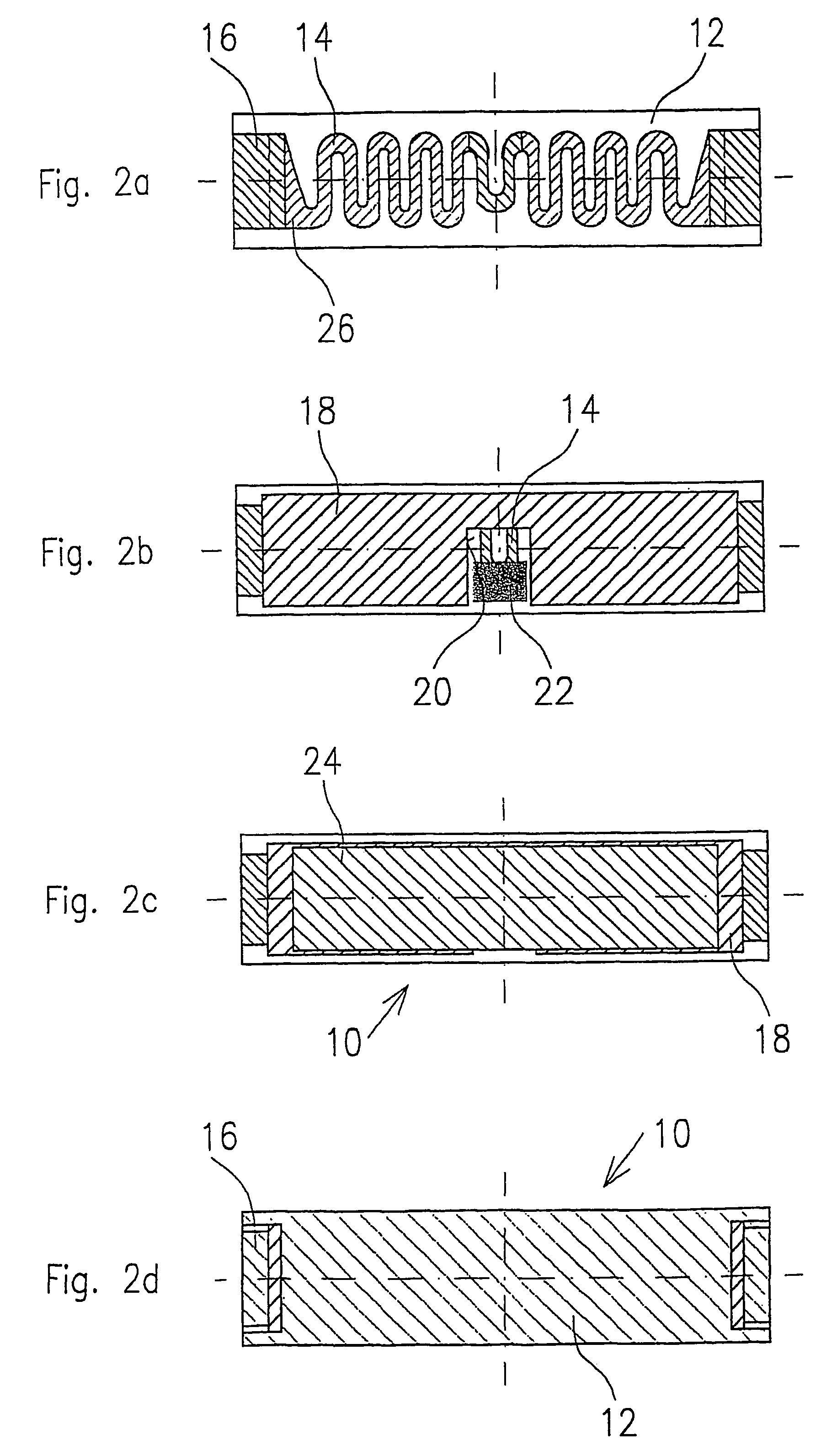
[0013]In a preferred embodiment of the fuse device, the thick film fusible conductor extends, at least in a central section, between the connecting surfaces in a serpentine shape (i.e. in loops in opposite directions). It is thus possible to increase the length of the fusible conductor, which has a relatively large cross-sectional area, with a small size of the
substrate surface. With this
sizing possibility, different rated currents can be achieved with approximately the same momentary pulse resistance.
[0014]In a preferred embodiment of the fuse element in accordance with the invention, the cover layer has at least one window, which is arranged over a section of the fusible conductor. The section of the fusible conductor situated in the window is at least partially covered by a layer, which contains a substance, which, when heated, can act on the fusible conductor situated beneath it such that the electrical resistance of the section of the fusible conductor increases. The window can be of any desired shape but, when producing the
layers by a
screen printing process, is preferably of approximately rectangular shape with edges aligned in the
screen printing direction. The window can be formed exclusively on the fusible conductor layer or can be so wide that regions of the
substrate surface adjacent to the fusible conductor are also exposed. The substance in the layer applied in the window is, for instance, a
metal, which can diffuse into the fusible conductor. For instance, the fusible conductor contains silver and the substance contains lead and / or
tin. The arrangement is so designed that in the event of predetermined current flows of predetermined minimum durations, heating of the fusible conductor and the layers applied thereon occurs, which is sufficient to permit the substance in the layer to act on the fusible conductor disposed beneath it. This locally increases its electrical resistance, which results in an increased
voltage drop, an increased local
power loss, further heating and finally in melting and / or vaporisation of the material of the fusible conductor. The current intensity, which results in the described manner in rupturing of the fusible conductor, is smaller than the current intensity, which would be necessary to melt the fusible conductor without the layer applied in the window. However, as a result of the aforementioned, time-consuming processes, a considerable longer time of the current flow is necessary until rupturing (
tripping) occurs; the fuse device becomes more slow acting.
[0015]The layer containing the
metal preferably has a good
thermal conductivity. This provides the possibility of rapidly dissipating heat which is produced in the fusible conductor beneath it as a result of momentary current pulses. The layer thus adopts a function of the cover layer lacking in the window. The entire section of the fusible conductor situated in the window is preferably covered by the layer so that the entire fusible conductor is covered either by the heat-dissipating cover layer or by the layer applied in the window. The layer can furthermore overlap with the edge of the window in order to compensate for technologically determined tolerances.

