Caster wheel having integrated braking means

a technology of braking means and caster wheels, which is applied in the field of caster wheels, can solve the problems of not being able to attach devices to the top, not being able to operate the operated brake electrically, and not being able to disclose the prior art of a caster wheel with an integrated electrical braking system, etc., and achieves the effects of simple design, effective and affordabl

Inactive Publication Date: 2010-05-11
LEWIS STEVEN +1
View PDF10 Cites 17 Cited by
  • Summary
  • Abstract
  • Description
  • Claims
  • Application Information

AI Technical Summary

Benefits of technology

[0016]A further object of the invention is to provide an electronic braking component for a caster wheel that will stop the caster wheel from rotating when the rake is engaged upon the caster wheel.
[0017]A further object of the invention is to provide a caster wheel with electrical braking means that is easy-to-use, simplistic in design, effective, and affordable.

Problems solved by technology

As will be discussed immediately below, no prior art discloses a caster wheel with an integrated electrical braking system.
However, the caster wheel braking system is not a component that screws into the top mounting bracket of the caster.
However, the manually operated brake is not electrically operated, and is not a component that is screwed into the top mounting bracket of the caster wheel.
However, the locking device does not attach to the top surface of the caster wheel mounting bracket.
While the above-described devices fulfill their respective and particular objects and requirements, they do not describe a caster wheel electronic braking system that screws into the top surface of the caster wheel mounting bracket.

Method used


Image

  • Caster wheel having integrated braking means
  • Caster wheel having integrated braking means
  • Caster wheel having integrated braking means

Examples


Embodiment Construction

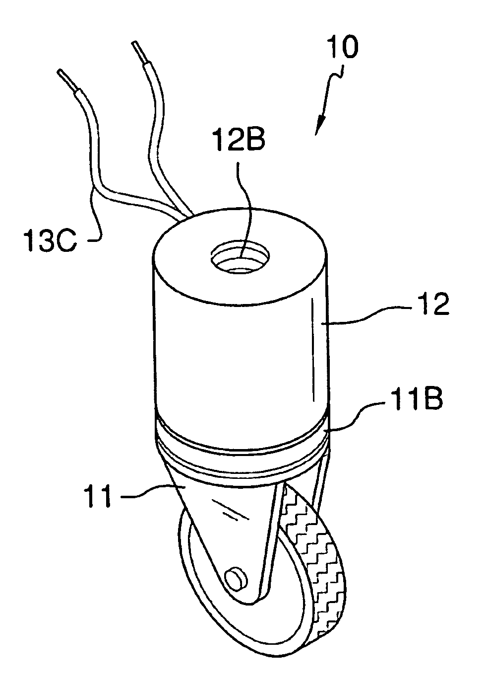
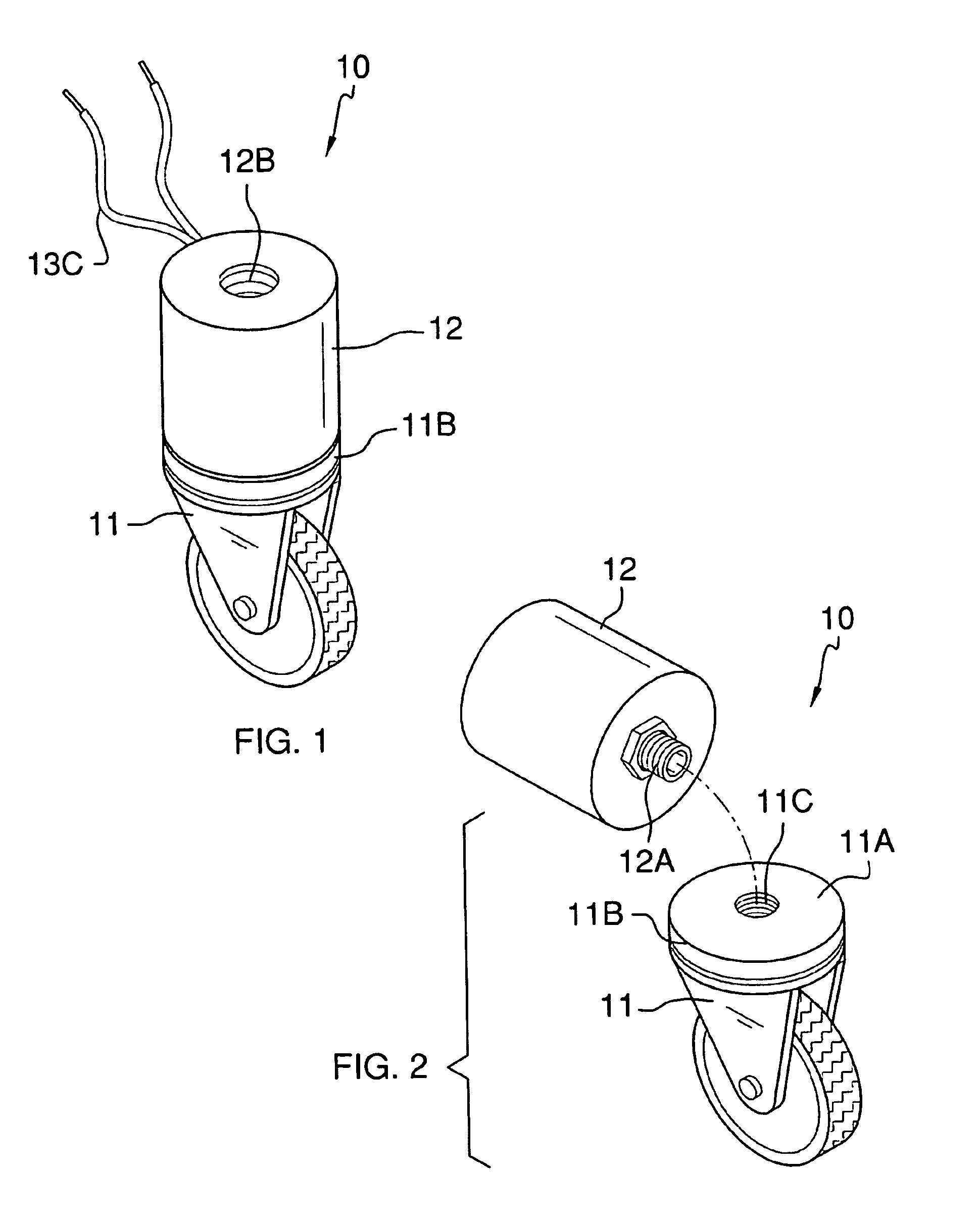
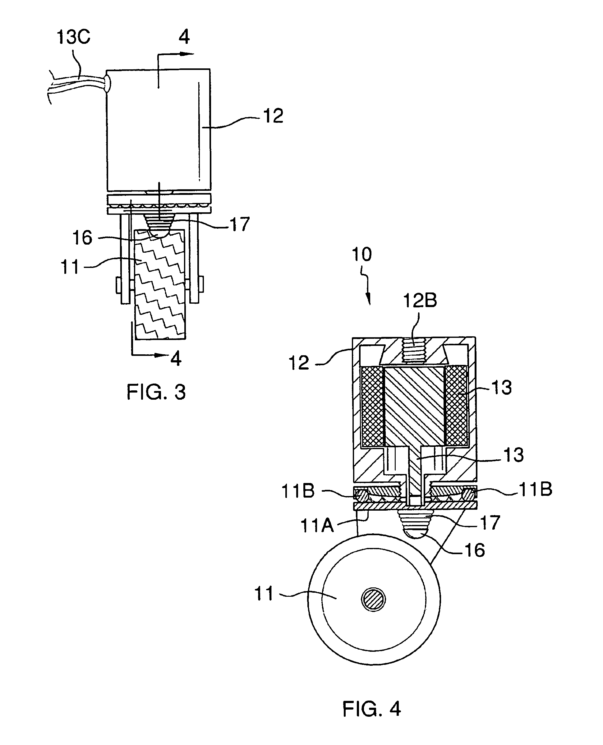
[0028]Detailed reference will now be made to the preferred embodiment of the present invention, examples of which are illustrated in FIGS. 1-6. A caster wheel having integrated electrical braking means 10 (hereinafter invention) includes a caster wheel 11 and an electrical braking component 12.

[0029]The electrical braking component 12 has a bolt 12A along a bottom surface and a threaded opening 12B along a top surface. The electrical braking component 12 also includes a solenoid 13, and a pin 14. The solenoid 13 is electrically wired via wiring 13C to a power switch 15, which is wired to a battery power source 16.

[0030]The caster wheel 11 has a mounting bracket 11A, and a ball bearing 11B. The electrical braking component 12 is secured to the caster wheel 11 by screwing the bolt 12A of the electrical braking component 12 into a threaded opening 11C on the mounting bracket 11A.

[0031]The ball-bearing 11B of the caster wheel 11 enables the caster wheel 11 to rotate about the mounting b...


PUM


Abstract

The caster wheel having integrated electrical brake involves a standard caster wheel and an electronic braking component that screws into the top surface of the caster wheel mounting bracket. The electrical braking component includes a solenoid that moves a pin up and down to impact a spring-loaded brake mounted underneath the caster wheel mounting bracket.

Description

CROSS REFERENCES TO RELATED APPLICATIONS[0001]Not ApplicableSTATEMENT REGARDING FEDERALLY SPONSORED RESEARCH[0002]Not ApplicableREFERENCE TO APPENDIX[0003]Not ApplicableBACKGROUND OF THE INVENTION[0004]A. Field of the Invention[0005]The present invention relates to the field of caster wheels, more specifically, a caster wheel with an electrical braking system.[0006]B. Discussion of the Prior Art[0007]As a preliminary note, it should be stated that there is an ample amount of prior art that deals with caster wheels. As will be discussed immediately below, no prior art discloses a caster wheel with an integrated electrical braking system.[0008]The Lange Patent (U.S. Pat. No. 5,184,373) discloses a caster wheel for a dolly or a cart that has an electrically activated brake which prevents rolling and turning movement of the wheel. However, the caster wheel braking system is not a component that screws into the top mounting bracket of the caster.[0009]The Strong Patent (U.S. Pat. No. 7,1...

Claims


Application Information

Patent Timeline
Patent Type & Authority Patents(United States)
IPC IPC(8): B60B33/00
CPCB60B33/0039B60B33/0049B60B33/0057B60B33/0068B60B33/0081B60B33/021B60B33/0073Y10T16/18Y10T16/195
Inventor LEWIS, STEVENLEWIS, CRYSTAL
Owner LEWIS STEVEN
Why Eureka
Try Eureka