Common payload rail for unmanned vehicles

a payload rail and unmanned vehicle technology, applied in the field of common payload rails, can solve the problems of compromising the effectiveness of the host unmanned vehicle, complex and costly modifications to the internal system of the vehicle, and the handling system is usually unique and expensive to construct and install, so as to reduce the hydrodynamic drag and reduce the vehicle. the effect of reducing the modification of the payload

Inactive Publication Date: 2010-05-25
NAVY AS REPRESENTED BY THE SCRETARY OF THE
View PDF6 Cites 30 Cited by
  • Summary
  • Abstract
  • Description
  • Claims
  • Application Information

AI Technical Summary

Benefits of technology

[0005]The present invention provides a common payload rail to connect external payloads to a UV such as a UUV or USV. The common payload rail has a vehicle interface module having a conforming surface rigidly secured to the unmanned vehicle and feed-through conduits. A functionality module is secured to the vehicle interface module and has internal interfacing components to minimize or eliminate any modifications to the payload and vehicle. A payload interface module having feed-through conduits is secured to the functionality module and has longitudinally extending rail structure sized to engage correspondingly shaped longitudinally extending receiving means on the payload. The longitudinally extending rail structure is shaped to extend into the longitudinally extending receiving means on the payload to arrest lateral displacement between the payload interface module and the payload. At least one securing mechanism on the payload interface module is disposed to engage the payload to arrest longitudinal displacement between the payload interface module and the payload. The feed-through conduits extending through the payload interface module and the vehicle interface module receive select ones of electrical conductors and optical fibers for power and data transmission and other communication requirements of the payload, functionality module, and unmanned vehicle. Some of the feed-through conduits can include tubes to transfer fluids between the payload, functionality module, and unmanned vehicle. The vehicle interface module, functionality module and payload interface module have essentially protuberance-free outer surfaces provided with tapered leading and trailing edges to reduce hydrodynamic drag. The longitudinally extending rail structure has a cross-sectional L-shape and the longitudinally extending receiving means is an L-shaped channel sized to slideably receive the L-shaped longitudinally extending rail structure. Preferably, the longitudinally extending rail structure is a pair of upward-extending, sliding-rail structures extending in an inverted, oppositely-facing L-shaped cross-sectional configuration and longitudinally extending on the payload interface module. The longitudinally extending receiving means is shaped as a pair of L-shaped channels that longitudinally extend in the lower part of the bottom assembly of the payload. The L-shaped channels are slightly larger than the pair of L-shaped sliding rail structures to allow the L-shaped sliding rail structures to be inserted in and contiguously slid within the L-shaped channels. The internal components' of the functionality module can include a variety of self-contained internal power source components to power its own internal components and the external payload. Computer data and signal processing components, including data storage components, to store and process the data sensed and collected by the payload can be included, and sensor components can be included to provide input data to augment the unmanned vehicle and the external payload; the computer components, including data processing and data storage components, may also be arranged to make the functionality module a payload of its own.

Problems solved by technology

This procedure frequently required space that may not be available and often involved extensive and costly modifications to internal systems in the vehicle.
The added-on support and handling systems are usually unique and expensive to construct and install and can compromise the effectiveness of the host unmanned UV.

Method used


Image

  • Common payload rail for unmanned vehicles
  • Common payload rail for unmanned vehicles
  • Common payload rail for unmanned vehicles

Examples


Embodiment Construction

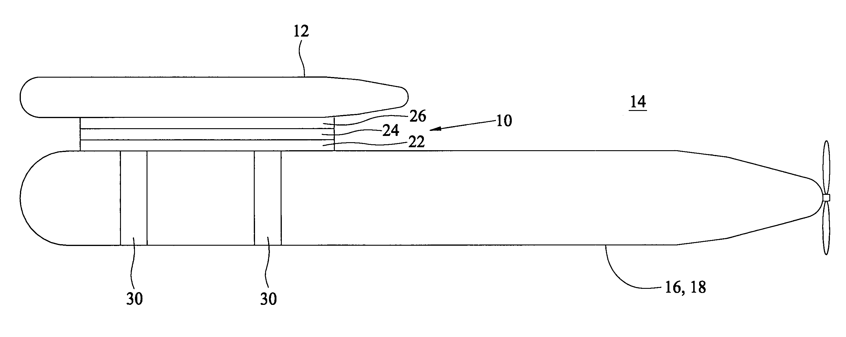
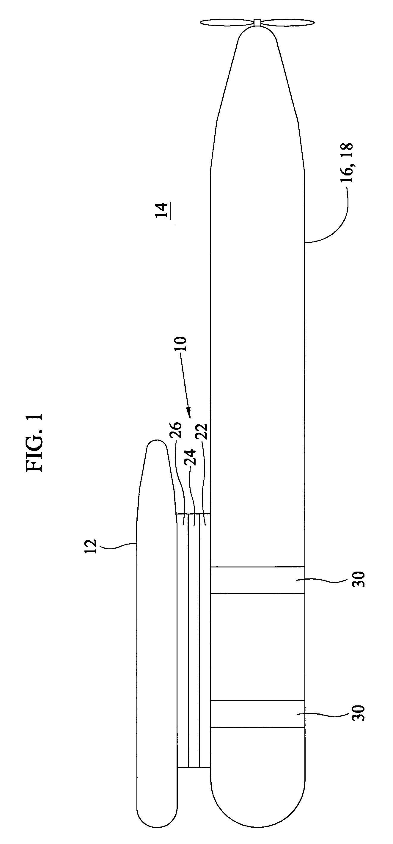
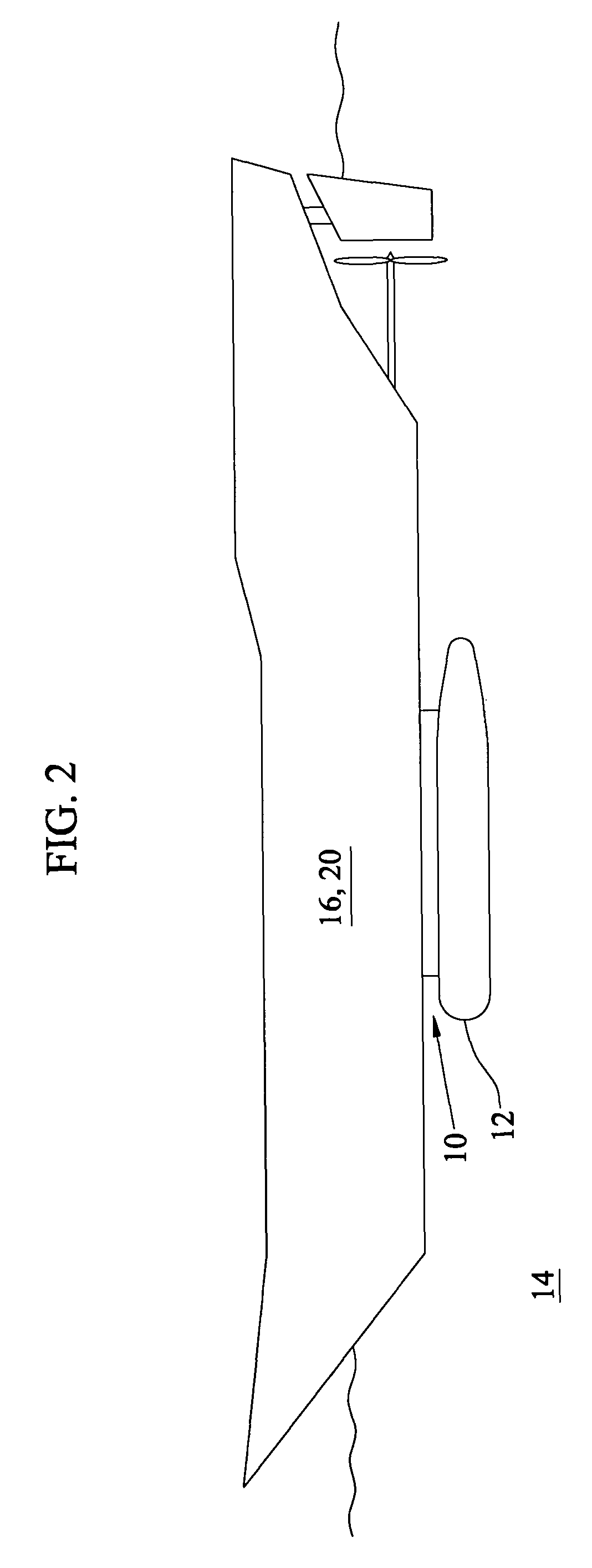
[0021]Referring to FIGS. 1 and 2, common payload rail 10 of the invention is used to externally mount a variety of payloads 12 submerged in water 14 on an unmanned vehicle (UV) 16 such as an unmanned undersea vehicle (UUV) 18 or an unmanned surface vehicle 20. Common payload rail 10 provides a means to secure and add payload capability externally to host vehicle UVs with minimal effort and virtually no internal modifications of the UVs and no requirements to occupy space inside the UVs. In other words, common payload rail 10 attaches externally to the surface of host vehicles such as UUV 18 or USV 20, as well as on manned vessels and crafts, and then provides a standard mechanical, electrical, electronic, and hydraulic mating surface for external payloads 12 that are designed and built to meet the common mating interface standard of common payload rail 10.

[0022]Referring also to FIGS. 3 and 4, common payload rail 10 is schematically depicted as having three mutually connectable modu...


PUM


Abstract

A common payload rail externally supports a submerged payload from an unmanned marine vehicle. A vehicle interface module has a conforming surface rigidly secured to the unmanned vehicle and feed-through conduits. A functionality module is secured to the vehicle interface module and contains internal interfacing components to minimize or eliminate any modifications to the payload and vehicle. A payload interface module having feed-through conduits is secured to the functionality module and has longitudinally extending rail structures sized to engage correspondingly shaped longitudinally extending receiving means on the payload. The longitudinally extending rail structures are shaped to extend into longitudinally extending receiving means on the payload to arrest lateral displacement between the payload interface module and the payload and at least one securing mechanism on the payload interface module is disposed to engage the payload to arrest longitudinal displacement between the payload interface module and the payload.

Description

STATEMENT OF GOVERNMENT INTEREST[0001]The invention described herein may be manufactured and used by or for the Government of the United States of America for governmental purposes without the payment of any royalties thereon or therefor.BACKGROUND OF THE INVENTION[0002]This invention is for a common payload rail for securing an added payload capability to increase the versatility of unmanned vehicles (UV). More particularly, this invention secures an added payload capability externally to unmanned systems such as unmanned undersea vehicles (UUVs) and unmanned sea-surface vehicles (USVs) with minimal modifications required to the internals of the unmanned system.[0003]Contemporary methods for increasing or improving the payloads for UUVs usually involve the insertion of additional payloads within the system. This procedure frequently required space that may not be available and often involved extensive and costly modifications to internal systems in the vehicle. Later developed exte...

Claims


Application Information

Patent Timeline
Patent Type & Authority Patents(United States)
IPC IPC(8): B63B21/66
CPCB63G8/42
Inventor PORTMANN, HELMUTMORITZ, ELAN
Owner NAVY AS REPRESENTED BY THE SCRETARY OF THE
Why Eureka
Try Eureka