Auxiliary marine vessel propulsion system

a technology for auxiliary marine vessels and propulsion systems, applied in marine propulsion, propulsive elements, vessel construction, etc., can solve the problems of a certain amount of hydrodynamic drag on the rudder, and achieve the effects of high torque, efficient operation, and increased power

Inactive Publication Date: 2012-04-05
SAUDI ARABIAN OIL CO
View PDF5 Cites 6 Cited by
  • Summary
  • Abstract
  • Description
  • Claims
  • Application Information

AI Technical Summary

Benefits of technology

[0029]It should also be understood that the orientation of the blades of the propeller can be adjusted relative to the drive shaft in order to attain more efficient operation, for example, to increase power when initiating movement from a stopped position, i.e., high torque and lower RPM, or to increase speed, i.e., low torque and relatively higher RPM when the vessel is underway.
[0030]It is known in the art to install a generally tubular stationary duct between the propeller and the vessel's stern to modify the wake field of full-form vessels such as tankers in order to improve fuel efficiency. In accordance with a further embodiment of the invention, a two-part moveable duct is mounted co-axially with the main propeller drive shaft between the propeller and the stern to provide in a first position, an open body formed of curvilinear segments to modify the wake form when the vessel is being powered by the main propeller, and in a second position, a truncated conical surface, with the smaller end forward towards the hull and relatively closer to the drive shaft, and the aft end defining an opening adjacent to the path circumscribed by the rotation of the ends of the main propeller blades. In the second position the conical surface serves to deflect the water outwardly to thereby by-pass the stationary blades of the main propeller and reduce the hydrodynamic drag on the vessel.

Problems solved by technology

This positioning of the rudder creates a certain amount of hydrodynamic drag.

Method used


Image

  • Auxiliary marine vessel propulsion system
  • Auxiliary marine vessel propulsion system
  • Auxiliary marine vessel propulsion system

Examples


Embodiment Construction

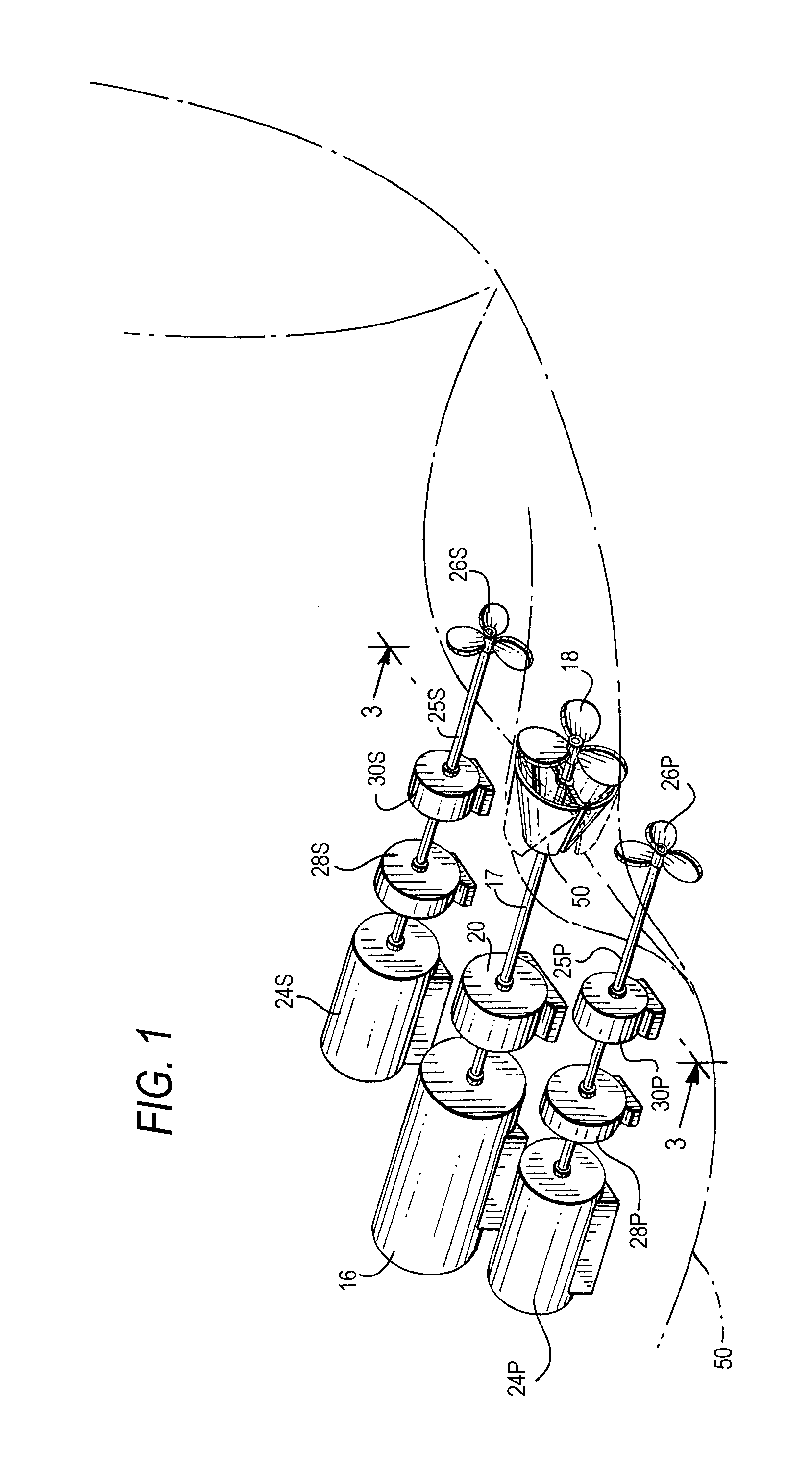
[0037]Referring to FIG. 1, a propulsion system 10 for a merchant vessel or the like is schematically depicted, including a main propulsion and drive subsystem 12 and a pair of auxiliary propulsion drive subsystems 14a and 14b, collectively referred to as 14, that can be operated independently of the main propulsion and drive subsystem 12. Generally, the main propulsion and drive subsystem 12 propels the vessel under normal operating conditions in accordance with known and conventional practices. According to the present invention, if the main propulsion drive subsystem 12 fails, or when the main propulsion drive subsystem 12 must be shut down for routine or unscheduled maintenance while at sea, the auxiliary propulsion drive subsystem 14 is used to propel the vessel, thereby offering reliable back-up propulsion. As will be understood by one of ordinary skill in the art, in a preferred embodiment the pair of auxiliary systems 14a and 14b flank the main drive system 12 at correspondin...


PUM


Abstract

The main propulsion and drive system of a merchant vessel such as a freighter or tank vessel, or a military vessel is supplemented by an auxiliary propulsion and drive system that includes at least one, but preferably a pair of auxiliary propellers that flank the main propeller at port and starboard positions and each of which are attached via a drive shaft through a gear train, which can optionally include a clutch mechanism, to an auxiliary motor or motors. In order to reduce the drag when the main propeller is disabled, segments of a wake field modifying propeller duct are mounted for repositioning to form at least a partial housing or cowling that diverts the water over the exterior surface of the duct and minimizes contact with the stationary blades of the main propeller as the vessel moves through the sea when powered by the auxiliary propulsion system.

Description

RELATED APPLICATIONS[0001]Not applicableBACKGROUND OF THE INVENTION[0002]1. Field of the Invention[0003]This invention relates to vessel propulsion systems, and more particularly to an auxiliary vessel propulsion system employing one or more controllable pitch propellers.[0004]2. Description of Related Art[0005]Propellers have been the primary mode of propulsion for merchant marine and military vessels since they replaced paddle-wheel and wind-driven sailing vessels in the early 20th century. While the scale, materials of construction, shape and engines have developed substantially over the past 100 years, the configuration of choice has essentially remained constant—single engine / single propeller design.[0006]The tremendous scale and complexity of primary drive engines requires scheduled and unscheduled maintenance for optimum operation. For proper service, the vessel should be anchored or drifting. Additionally, engine failure is a problem which, while not necessarily very common,...

Claims


Application Information

Patent Timeline
Patent Type & Authority Applications(United States)
IPC IPC(8): B63H21/17B63H3/00B63H5/14B63H1/14B63H20/14
CPCB63B2241/10B63H3/00B63H5/08Y02T70/70B63H23/30B63J2003/046Y02T70/542B63H5/16Y02T70/00Y02T70/50
Inventor AL BABTAIN, AHMED ABDULRAHMAN A.
Owner SAUDI ARABIAN OIL CO
Why Eureka
Try Eureka