Sheet conveying device and image forming apparatus

a conveying device and a technology for forming apparatus, applied in the direction of registering devices, thin material processing, article separation, etc., can solve the problems of lowering the accuracy of aligning a sheet in conveying, the apparatus itself becomes large, and the manufacturing cost of the apparatus is high

Inactive Publication Date: 2010-05-25
RICOH KK
View PDF29 Cites 44 Cited by
  • Summary
  • Abstract
  • Description
  • Claims
  • Application Information

AI Technical Summary

Problems solved by technology

In addition, with the above configuration, because the stopper and the conveying unit each need a driving unit, the apparatus itself becomes large and the manufacturing cost thereof becomes high.
Consequently, when the sheet conveying position correction of the sheet 39 is performed in the main scanning direction by the lateral registration rollers 32, the resistance on the sheet conveying path interferes with the movement of the sheet 39 in the main scanning direction, which results in lowering the accuracy of aligning a sheet in conveying.
Therefore, if there are various types of sheets with different lengths, unnecessary time loss is generated in conveying depending upon the length of the sheet, which may lower the conveying efficiency.
Therefore, the waiting time in the case of the shorter sheet becomes long compared to the case of the longer sheet, thereby causing a time loss.

Method used


Image

  • Sheet conveying device and image forming apparatus
  • Sheet conveying device and image forming apparatus
  • Sheet conveying device and image forming apparatus

Examples


Embodiment Construction

[0033]Exemplary embodiments of the present invention are explained below with reference to the accompanying drawings.

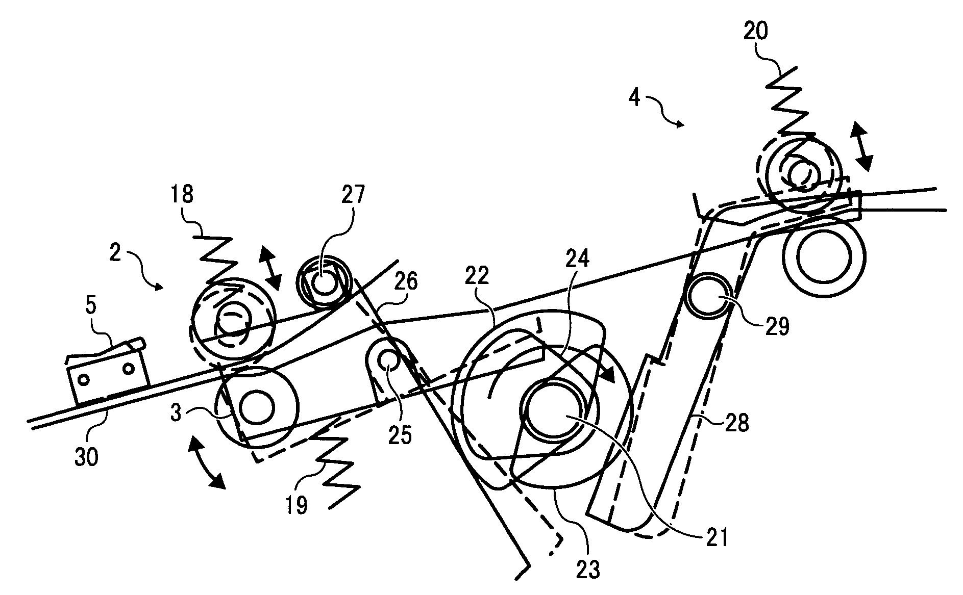
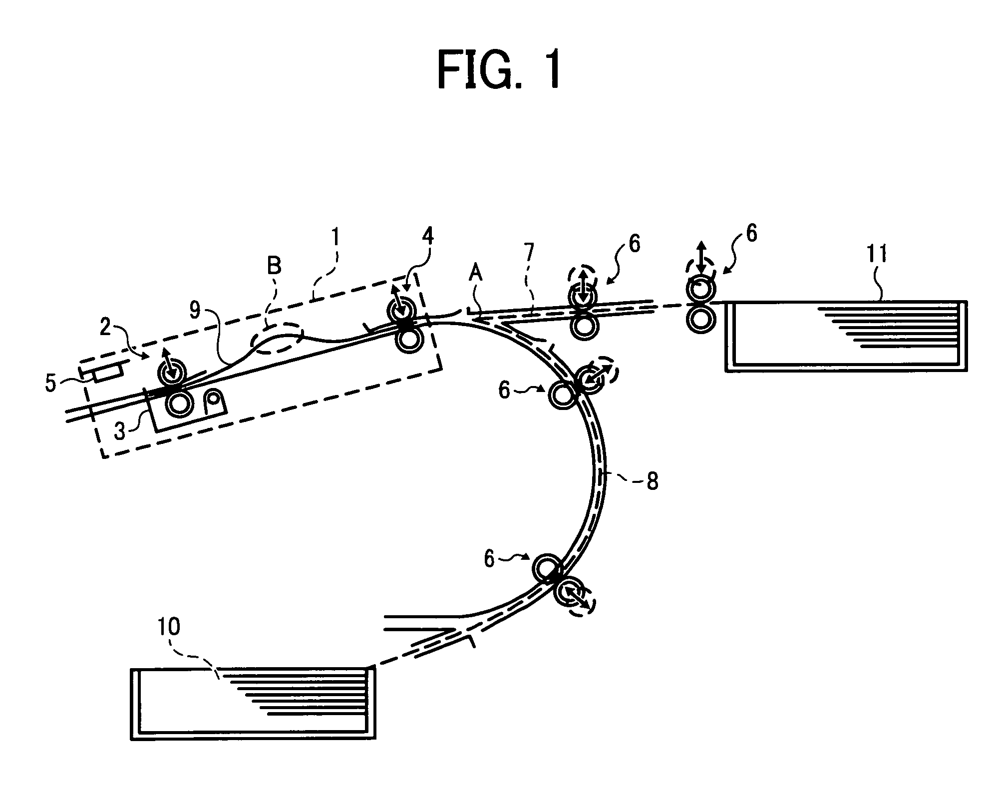
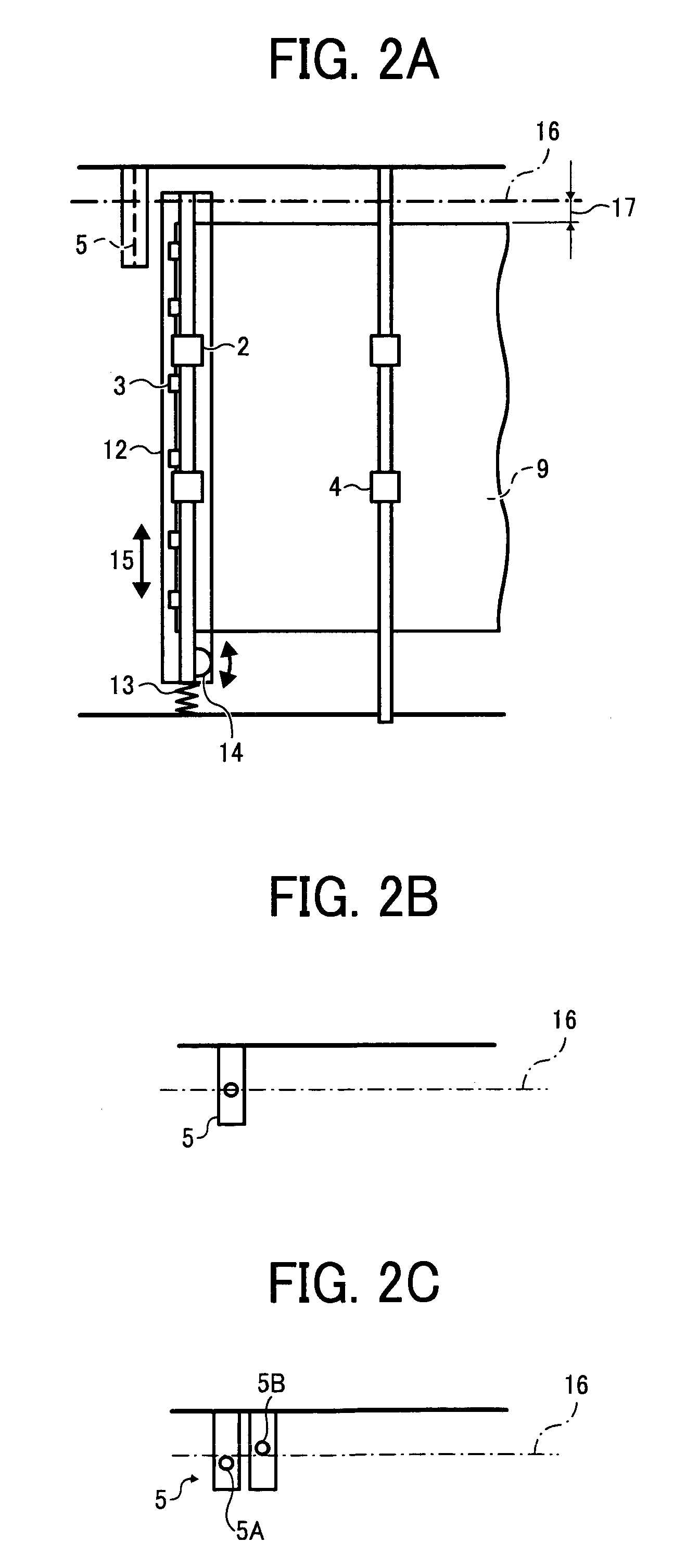
[0034]FIG. 1 is a schematic diagram of one example of a sheet conveying device according to an embodiment of the present invention. The sheet conveying device includes a sheet aligning unit 1 including a pair of lateral registration rollers 2 as a first pair of rollers, a stopper 3 including a claw at its one end, a pair of feeding rollers 4 as a second pair of rollers, and a detection sensor 5, pairs of conveying rollers 6 as third pairs of rollers, a straight sheet-conveying path 7, a curved sheet-conveying path 8, and sheet trays 10 and 11.

[0035]Sheets 9 in the sheet tray 10 arranged outside the apparatus body and the sheet tray 11 arranged in the apparatus body are conveyed to the feeding rollers 4 through the sheet-conveying paths 7 and 8, respectively, by the conveying rollers 6 provided on the sheet-conveying paths 7 and 8. The distance between adjacent pairs o...


PUM


Abstract

A cam unit includes three cams fixed on a common cam shaft for moving a pair of feeding rollers, a pair of lateral registration rollers, and a stopper unit, respectively. A control unit corrects a lateral registration of a sheet whose skew is corrected by the stopper unit, based on a detection result of a detecting unit that detects a position of a side edge of the sheet, while conveying the sheet, controls the rollers not nip the sheet at least during the lateral registration, and controls rotations of the cams according to a length of the sheet.

Description

CROSS-REFERENCE TO RELATED APPLICATIONS[0001]The present application claims priority to and incorporates by reference the entire contents of Japanese priority document 2007-145395 filed in Japan on May 31, 2007.BACKGROUND OF THE INVENTION[0002]1. Field of the Invention[0003]The present invention relates to a sheet conveying device and an image forming apparatus, and more particularly, to a mechanism for performing a position correction in a main-scanning direction and a skew correction at a leading edge of a sheet.[0004]2. Description of the Related Art[0005]An image forming apparatus such as a laser printer feeds sheets such as printing papers accommodated in a feeding unit one by one, transfers a toner image formed on a photosensitive drum, a photosensitive belt, or the like onto the sheet at a transfer position, and fixes the toner image to the sheet, thereby obtaining the sheet with the toner image thereon.[0006]In such image forming apparatus, a registration mechanism including...

Claims


Application Information

Patent Timeline
Patent Type & Authority Patents(United States)
IPC IPC(8): B65H5/02
CPCB65H7/02B65H9/06B65H9/10B65H2403/512B65H2511/11B65H2511/20B65H2511/242B65H2513/53B65H2220/01B65H2220/03B65H2220/02B65H2511/24B65H2513/52
Inventor SHOJI, YUTAKASHIRAKAWA, JUNJIMUNEYASU, TAKAYUKI
Owner RICOH KK
Why Eureka
Try Eureka