Device for driving a closing or sun-protection screen and installation comprising such a device

a technology for sun protection screens and devices, which is applied to curtain suspension devices, curtain accessories, building components, etc., can solve the problems of tightness or sealing of components, tightness or sealing of electronic processing units that they contain with respect to ambient environment, and type of devices that are likely to be installed outside and thus subject to bad weather

Active Publication Date: 2010-06-01
SOMFY SAS
View PDF11 Cites 26 Cited by
  • Summary
  • Abstract
  • Description
  • Claims
  • Application Information

AI Technical Summary

Benefits of technology

[0010]The tightly sealed partition of the device according to the invention makes it possible hermetically to define respective hollow housings for the mobile part having elements representative of the position and / or the displacement of the tube and for at least the electronic processing unit that is sensitive to humidity and water coming from outside the device. This partition is secured to or integral with the head fixed with respect to the bearing structure. Such a structure does not complicate assembly and installation of the device.

Problems solved by technology

Although the afore-mentioned device is satisfactory as to its function of automatic control of the drive of the screen, it presents a drawback concerning its tightness or sealing of components, particularly the tightness or sealing of the electronic processing unit that it contains with respect to the ambient environment.
In effect, this type of device is likely to be installed outside and thus to be subjected to bad weather.
This results in considerable risks of water infiltrating inside the tube and therefore reaching the electronic processing unit and the electric motor, particularly via the opening necessary for the kinematic links between a transmission means and a ring that rotatably supports the tube.
It is difficult to seal this opening tight due to the mobility of the ring which, in addition, must present axial and radial clearances sufficient in order, on one hand, to match winding tubes of various origins whose dimensions are imprecise due to their mode of manufacture and, on another hand, to compensate for clearances of expansion associated with the functioning of the motor and climatic conditions.
These solutions are not economical as they require more voluminous parts, particular geometries at the level of the elements in contact and / or a complex process of assembly.
In the device known from EP-A-0 965 724, the ring of magnets is expensive and the precision of measurement depends on the angular deviation between the peripheral magnets.
This deviation being fixed by the diameter of the support which depends on the type of motor used, it cannot be adjusted easily.
The tightness of the sensors is thus ensured but this solution does not guarantee tightness of the conductors connecting the sensors to an electronic unit for processing the signals furnished by these sensors.

Method used


Image

  • Device for driving a closing or sun-protection screen and installation comprising such a device
  • Device for driving a closing or sun-protection screen and installation comprising such a device
  • Device for driving a closing or sun-protection screen and installation comprising such a device

Examples


Embodiment Construction

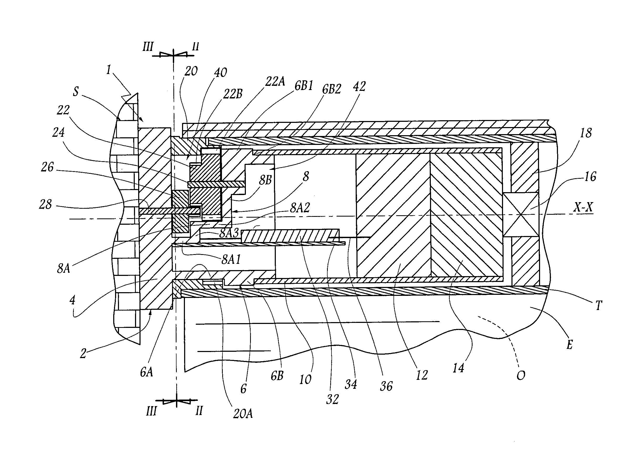
[0019]Referring now to the drawings, the installation of FIG. 1 comprises a closing or sun-protection screen E, intended to be selectively wound around a substantially horizontal tube T of axis X-X fixed with respect to the masonry of a fixed structure S in which is made an opening O to be obturated with the screen E. The winding tube T constitutes a member for displacement of the screen E and is mounted on a device 1 for reversible drive of the screen E.

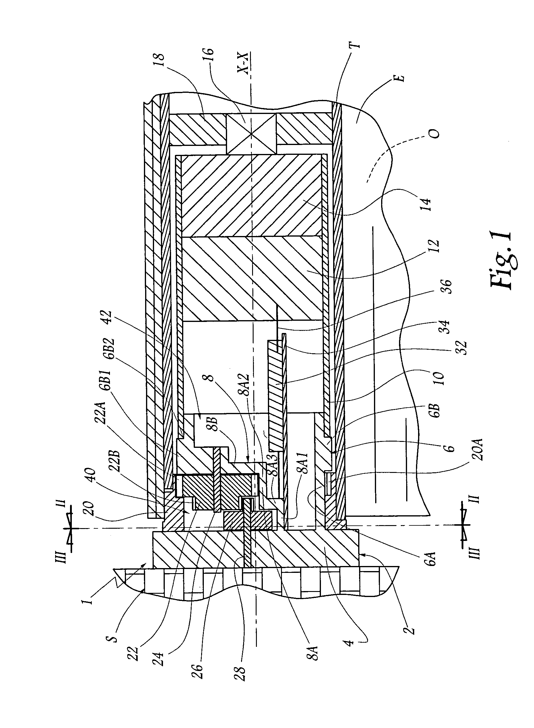
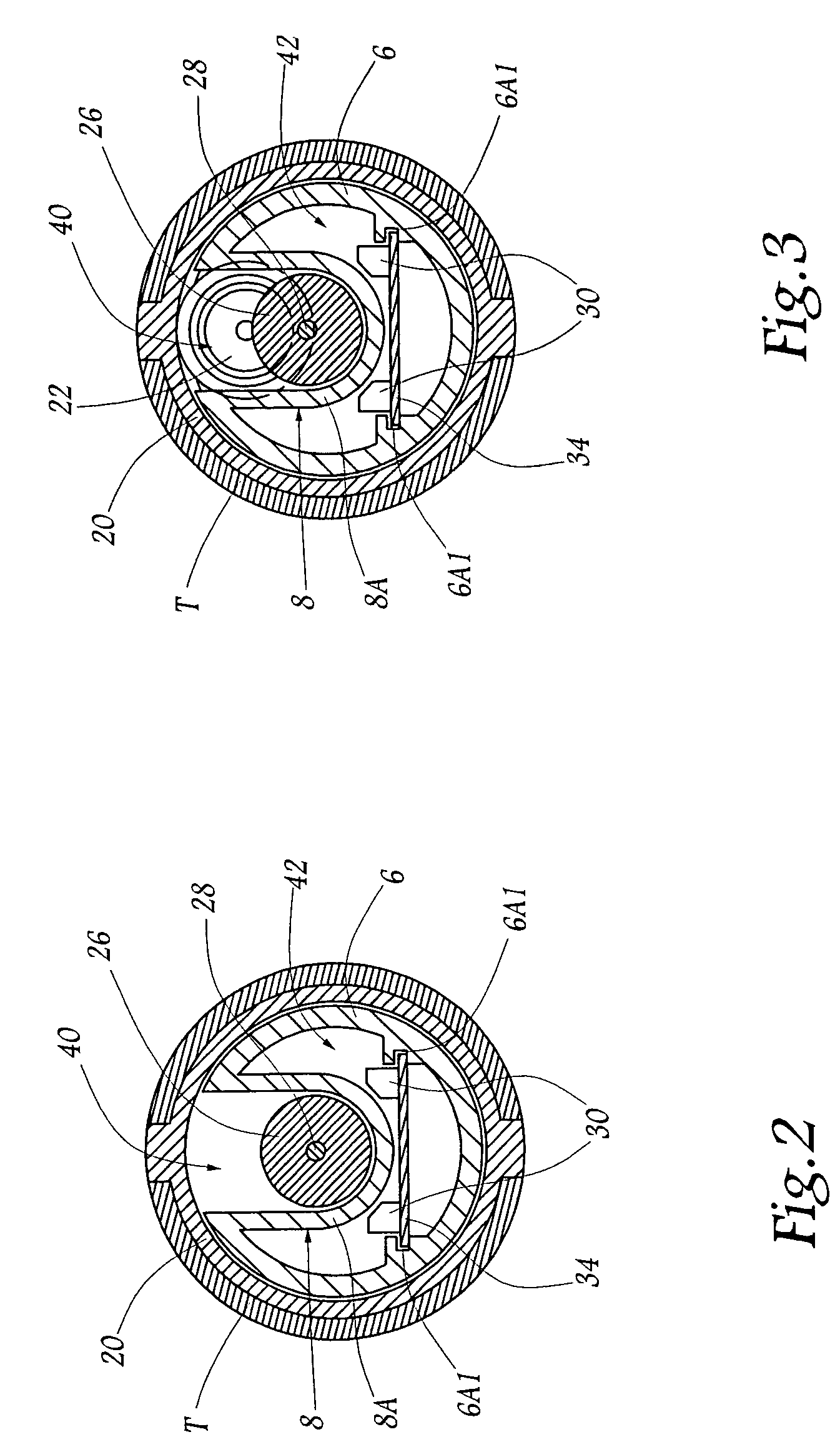
[0020]This device 1 comprises a head 2 rigidly mounted on the masonry of the structure S. As shown in FIGS. 1 to 4, this head 2 comprises a solid base 4 in the form of a disc centered on axis X-X and mounted on the masonry and, on the side opposite the structure S, an annular skirt 6 centered on axis X-X.

[0021]For convenience, the term “front” in the following description will mean “directed towards the masonry”, i.e. directed towards the left in FIG. 1, while the term “rear” corresponds to the opposite direction. Moreover, for reas...


PUM


Abstract

A device including a tube for winding and unwinding a screen which is controlled in rotation by a gear motor and which is supported on a fixed head and wherein a rotational part mounted within the tube is kinematically linked to rotate with the tube with the part including elements that are used to reflect a position of the rotational part and which elements are detected by senors that are connected to an electronic processing unit. A tightly sealed partition secured to the head is further provided to define, on one side, a first compartment for receiving at least the rotational part and, on the other side, a second compartment for receiving at least the electronic processing unit.

Description

FIELD OF THE INVENTION[0001]The present invention relates to a device for driving a closing or sun-protection screen, as well as to a closure or sun-protection installation incorporating such a device.[0002]A closure installation is understood to mean structures having openings that are closed or covered by doors, blinds, shutters and equivalent devices.BACKGROUND OF THE INVENTION[0003]In an installation having an opening, a screen, which may be a supple screen body or a rigid or semi-rigid panel, is displaced opposite the opening in order to selectively obturate the latter. In order to make the movement of the screen automatic, it has been proposed in the past to equip it with means for automatically detecting a position and / or a displacement of the screen and thus to use pre-defined positions to control electrical power supply to a screen drive motor, particularly the top and bottom ends of stroke and possibly intermediate positions in which the electrical supply to the motor is i...

Claims


Application Information

Patent Timeline
Patent Type & Authority Patents(United States)
IPC IPC(8): A47G5/02E06B9/56E06B9/68E06B9/72E06B9/80
CPCE06B9/72E06B2009/6872
Inventor BEAU, STEPHANE
Owner SOMFY SAS
Why Eureka
Try Eureka